 EN
EN
 English
 русский
 Español


")


Conductor design and flexibility: strand count, diameter & trade-offs
For copper-core PVC insulated and sheathed cables the mechanical and electrical behavior starts with conductor geometry. Increasing strand count (many fine strands vs. few thick strands) improves flexibility and fatigue life under repeated flex cycles, but changes DC resistance slightly due to surface oxidation and contact area in terminations. In practical terms for a flexible shielded cable used in moving machinery or robotics, designers commonly move from Class 2/5 stranding toward finer Class 6/7 stranding. This reduces the minimum bending radius and dramatically lowers conductor work-hardening over repeated flex.
Practical selection rules
- If cable must flex continuously (e.g., drag chain), choose higher strand counts and evaluate flex-life to >1 million cycles.
- For fixed wiring with occasional bending, coarser strands reduce cost and simplify terminations.
- When sizing for voltage drop, use conductor resistance at operating temperature (not room temperature) — stranded conductors warm faster under load.
Insulation thickness, voltage rating and thermal considerations
PVC insulation systems are specified by both their electrical withstand and thermal class. Thickness directly affects dielectric strength, but thermal properties of the compound determine current-carrying capacity and permissible ambient. For shielded flexible cables used near heat sources, select PVC compounds formulated for higher continuous operating temperatures (e.g., 90°C rated compounds) and consider thicker insulation for transient overvoltage margins.
Design tips for improved performance
- Specify insulation thickness per IEC/NEC tables for the intended voltage class and add 10–20% when transient protection is a concern.
- Where heat dissipation is limited (bundled cables), derate ampacity and consider thermal stabilizers in the PVC compound.
- UV-stabilized PVC formulations or additional outer jackets help outdoors; otherwise, PVC will embrittle under long UV exposure.
Sheath materials, flame retardancy and environmental resistance
Standard PVC sheaths provide good abrasion resistance and cost-effectiveness, but their compound formulation controls flammability, smoke density, and toxicity. For industrial and public-space applications, low-smoke zero-halogen (LSZH) alternatives are sometimes required; however LSZH sacrifices some oil/abrasion resistance compared with engineered PVC blends. When specifying a copper-core PVC insulated & sheathed cable, clarify whether the project requires flame tests such as IEC 60332-1/3 or UL 1581 vertical tray tests — each test targets different fire behaviors.
When to insist on special sheaths
- Public transport, tunnels or enclosed spaces: require LSZH or tested low-smoke PVC.
- Outdoor installation: use UV-stabilized and weatherproof PVC blends or an additional TPU/PE jacket.
- Oil-rich industrial areas: choose oil-resistant PVC or elastomeric outer jackets to avoid softening and swelling.
Shielding methods for EMI control: foil, braid, and combined constructions
Shield selection must balance coverage, flexibility and grounding practice. Foil (aluminum/polyester) provides 100% coverage and is excellent at high frequencies but is mechanically fragile and reduces flex life if used alone on moving cables. Braid shields (tinned copper) offer mechanical robustness and good low-frequency performance, but typical coverage ranges from 60–95%; higher coverage increases stiffness. A combined foil + braid (foil underbraid) gives the best broadband protection while maintaining reasonable flexibility.
| Shield Type | Typical Coverage | Best Use | Flex Impact |
| Foil (Al/PET) | ~100% | High-frequency EMI, instrument cables | Delicate; reduces flex life if unsupported |
| Braid (tinned copper) | 60–95% | Power/low-freq noise, mechanical protection | Moderate; higher coverage = stiffer |
| Foil + Braid | 100% + 60–95% | Broadband EMI control, demanding installations | Best compromise; still reduces flexibility somewhat |
Shield termination and grounding practices
Correct shield termination preserves the shielding benefit: terminate at one end for signal lines to avoid ground loops; for power or long cable runs, bonded shields at both ends may be required with controlled grounding. Use compression or soldered drain wires for low-impedance connection; crimped mechanical terminations are common but must be verified with continuity and pull tests. When routing through connector housings, maintain shield continuity with metal backshells or dedicated shield clamps to minimize radiated emissions.
Installation practices: bending radius, clamping, and strain relief
Installation mistakes are a frequent cause of premature cable failure. For copper-core PVC insulated cables, adhere to minimum bending radius rules based on cable construction (flexible cables often specify 4× cable diameter for dynamic use, static installations may allow 8×). Excessive clamping pressure deforms insulation and can create hotspot points where fatigue concentrates. Use appropriately sized gland entries, set screw clamps with protective pads, and provide service loops where movement occurs.
- Always follow the manufacturer-specified dynamic bending radius; when in doubt, increase the radius rather than decrease it.
- Avoid sharp edges at entry points — use grommets or rounded flanges to prevent chafing.
- For moving installations, route cables in dedicated trays or conduits to separate them from fixed wiring and sources of abrasion.
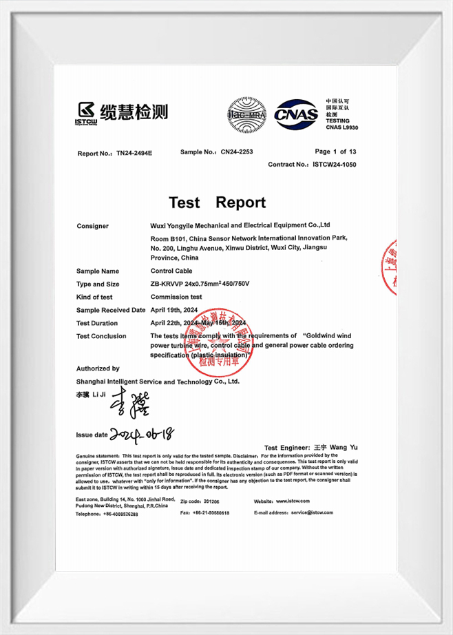
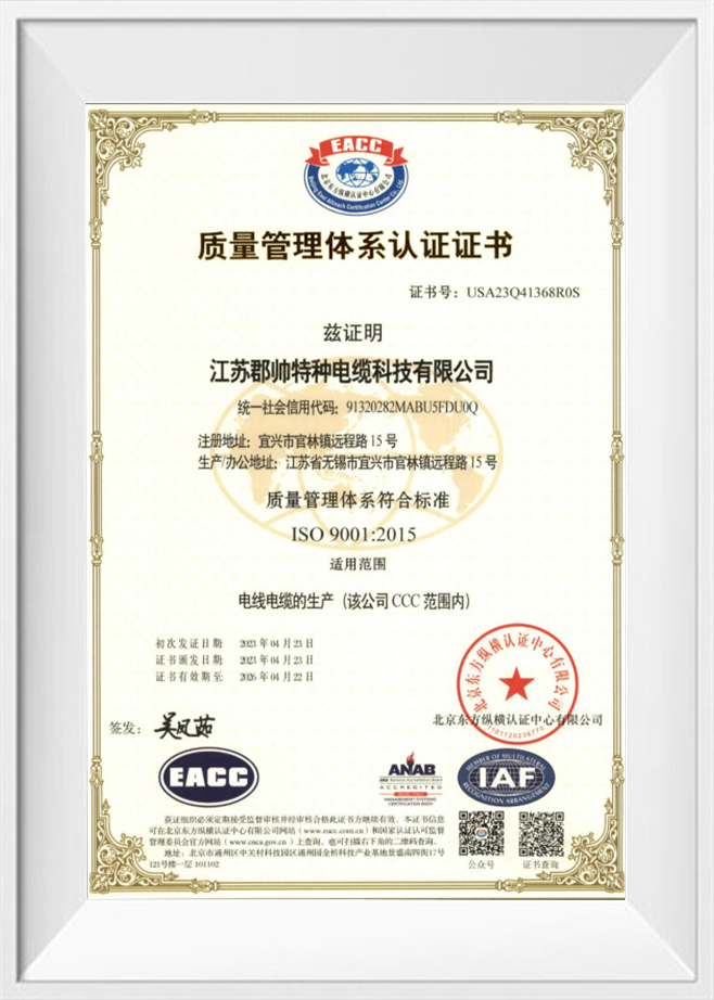
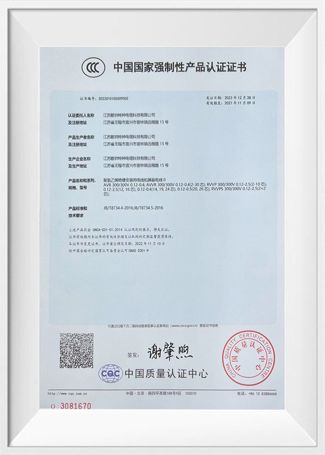
Testing, traceability and certifications: what to expect from a reputable supplier
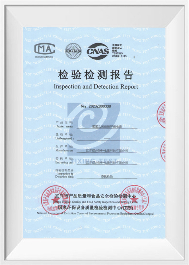
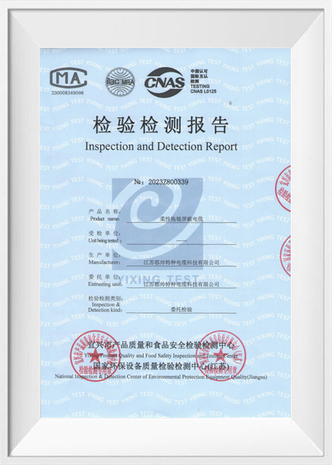
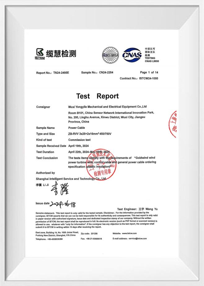
A reliable cable supplier will provide documented factory testing: conductor resistance, high-potential (hipot) tests, insulation resistance, continuity of shield, and mechanical tests for flex life when applicable. Traceability (lot numbers, material certificates) and third-party certifications such as CCC, UL, ISO9001 and CE are important signals of process control and compliance. For custom builds, request factory test reports and build-to-order test plans that reflect your application's electrical and mechanical stresses.
Recommended factory tests for shielded flexible cables
- DC resistance and conductor continuity — verify gauge and stranding.
- Hipot test between conductor and shield/earth to confirm insulation integrity.
- Shield continuity and coverage verification (visual + electrical) and braid coverage measurement where applicable.
- Flex life sampling for dynamic cables, with post-flex electrical checks to catch broken filaments.
As a manufacturer, I ensure Junshuai runs these key tests in our in-house labs and can provide certification copies on request — our advanced production and testing equipment, combined with CCC, UL, ISO9001 and CE credentials, allows us to tailor and validate cables to demanding specifications.
Customization considerations for special applications
When projects move beyond standard catalog items, practical customization points include: altered conductor metallurgy (oxygen-free copper for low-noise), colored or numbered inner jackets for simplified field identification, hybrid constructions that combine power and signal pairs with shared shield, and bespoke outer jackets for chemical resistance. Each change affects mechanical, electrical and EMC behavior, so a controlled design verification plan is essential.
Questions to define before ordering a custom run
- Will the cable be static, occasional flexing, or continuous motion?
- Are there environmental exposures (oil, UV, chemicals, salt spray)?
- What EMC attenuation levels are required across frequency bands?
- Is traceability, batch testing, or custom labeling required for regulatory reasons?
We work directly with customers to answer these questions and produce a tailored spec — if you need custom PVC insulated sheathed shielded flexible cable, I can walk you through the trade-offs and supply factory test documentation to match your application.
