 EN
EN
 English
 русский
 Español


Shielding strategies for noisy VFD environments
VFDs produce high-frequency switching voltages that can radiate and conduct along conductors. An effective shield does two jobs: it intercepts radiated emissions and provides a low-impedance return path for high-frequency leakage currents. For practical installations always treat the cable shield as an active part of the grounding system rather than cosmetic braid—terminate it solidly at the drive end and consider a second termination at a panel or local ground for long runs to minimize common-mode voltage buildup.
Single-end vs. both-end shield termination
Single-end termination (drive end only) usually reduces ground loop currents for moderate-length runs in industrial plants; both-end termination improves shielding effectiveness for radiated emissions on very long runs but may introduce circulating currents if the plant ground is noisy. In practice assess site grounding and measure leakage currents—if you detect high ground loop flows, revert to single-end at the drive with local bonding at the motor cabinet.
Cable construction choices and how they affect performance
The conductor material, insulation type, and shield geometry all change how the cable behaves with PWM outputs. Copper conductors are standard; however, stranding count and individual strand size affect flexibility and skin/ proximity effects at higher frequencies. Insulation with low dielectric constant and low loss tangent reduces capacitive coupling between conductors and lowers charging currents—this matters for long cable runs and for drives without output filters.
| Shield type | Attenuation (HF) | Flexibility | Recommended use |
| Aluminum-Mylar foil + drain | High (good coverage) | Moderate | Fixed runs where HF attenuation is important |
| Tinned copper braid | Moderate (depends on coverage %) | High | Flexible routing, armored assemblies |
| Foil + braid combination | Highest | Moderate | Critical EMI environments and long runs |
Installation best practices for long VFD cable runs
- Maintain physical separation from sensitive control/communication cables—if separation is impossible, route variable frequency drive cable in separate conduits or use grounded metallic segregation.
- Avoid coiling excess cable near drives; coils increase inductance and can cause overvoltage reflections on the motor terminals.
- Observe manufacturer-specified bend radius—tight bends can damage shield continuity and increase dielectric stress, reducing life under repetitive stress.
- Implement intermediate grounding points for very long metallic cable trays while monitoring for circulating currents; use bonding jumpers sized for high-frequency currents, not just steady-state fault currents.
Electrical characteristics that matter (and how to mitigate issues)
Capacitance, charging currents and motor heating
Cable-to-conductor and conductor-to-shield capacitances produce charging currents when the VFD switches. Charging currents cause extra losses in the motor and increase drive current readings. For long runs choose cables with lower capacitance per meter, or install dV/dt filters or sinusoidal output filters at the drive to reduce switching dv/dt and lower charging current into the motor.
Reflections, cable impedance and overvoltage at motor terminals
Rapid PWM edges see the cable as a transmission line; mismatches between drive output impedance and cable characteristic impedance create voltage reflections that appear as transient overvoltages at the motor. Solutions include controlling dV/dt (snubbers, filters), using cable with appropriate impedance, and keeping cable lengths within recommended limits for the drive (consult drive docs). For high-voltage or long-distance runs, output reactors can also help damp reflections.
Connector terminations, armor, and mechanical protection
Shield termination quality directly impacts EMC performance—use continuous 360° shield contact where possible and ensure the drain conductor or braid is soldered or crimped to maintain low impedance. When armor is present (steel wire or tape) bond armor to earth at one or both points depending on site grounding practice. Use proper strain relief to prevent shield or conductor pull-out; mechanical failures often masquerade as intermittent electrical faults.
Testing, certifications, and why they matter
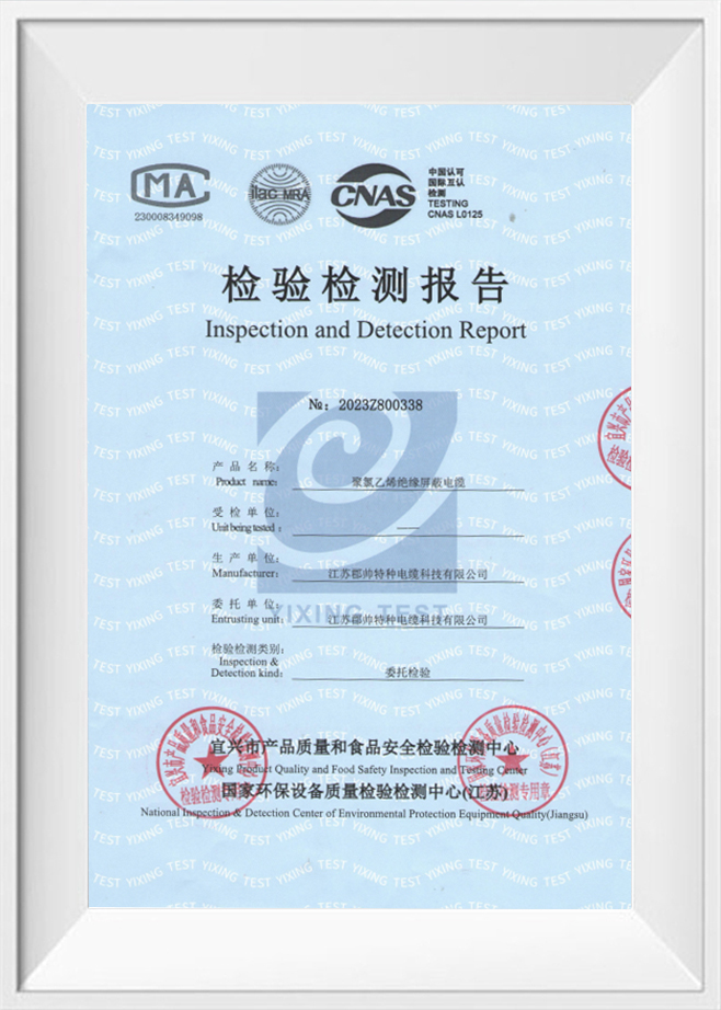
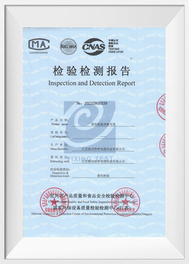
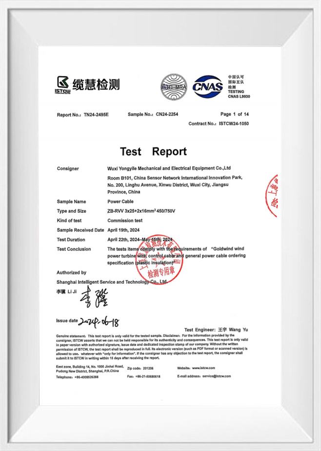
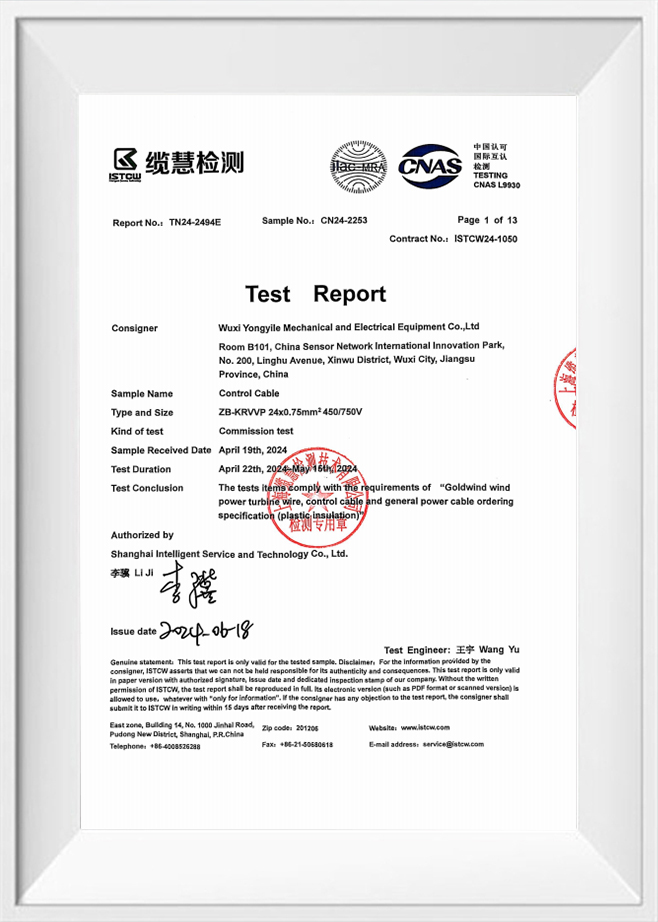
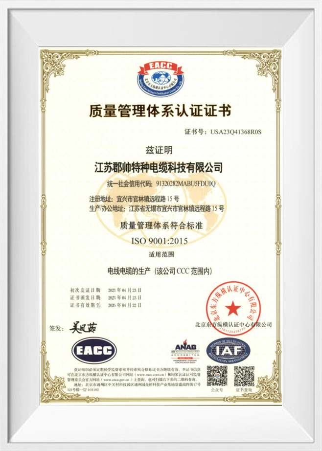
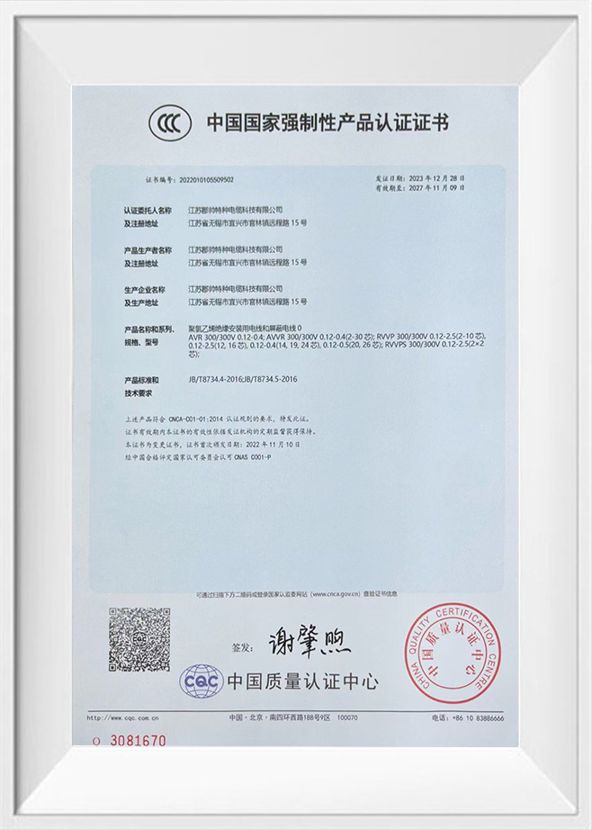
Verified performance through tests (impedance, capacitance, high-potential, shield continuity, and EMC emission tests) ensures cables behave predictably in VFD installations. Certifications such as UL and CE indicate compliance with recognized safety and EMC standards, while a robust ISO9001 quality system helps maintain consistency across production batches. We manufacture shielded VFD cable grades and our factory holds CCC, UL, ISO9001 and CE certifications—this allows us to support customized builds with traceable test records when projects demand it.
Common failure modes and on-site troubleshooting checklist
- Intermittent tripping: check shield terminations and continuity; poor bonds cause EMI to couple into control circuits causing nuisance trips.
- High motor bearing currents: verify shaft grounding measures, inspect cable shield connections and consider installing shaft grounding rings or insulated bearings where appropriate.
- Overtemperature at motor: measure charging current and compare against motor heating curves—if charging contributes, lower switching frequency or fit filters.
- Severe EMI complaints: perform a site survey with a near-field probe, review shield coverage (% braid), and consider upgrading to foil+braid composite shields or adding ferrite cores on the motor cable.
If you want, we can provide tailored cable construction recommendations (conductor stranding, shield type, jacket compound) for your application—we design and produce custom VFD shielded motor cables and can supply test reports and certificates on request. When reliability and EMC performance matter, a purpose-built cable from a certified manufacturer reduces commissioning time and long-term maintenance headaches.
