 EN
EN
 English
 русский
 Español
Continuous Flexing Automation Cable: Selection Guide for Engineers
 2026.07.22
 Industry News
Content
- 1 What is a Continuous Flexing Automation Cable?
- 2 Key Performance Parameters to Evaluate
- 3 Shielding Showdown: Braid vs. Foil for EMI Protection
- 4 Jacket Material Deep Dive: PVC, PUR, and TPE
- 5 Application-Specific Selection Matrix
- 6 The Role of Certifications (UL, CE) in Cable Selection
- 7 Total Cost of Ownership: Why Cheap Cables Cost More
- 8 When Standard Isn't Enough: Exploring Custom Cable Solutions
What is a Continuous Flexing Automation Cable?
A standard control cable fails after 50,000 bends in a cable chain. A continuous flexing automation cable delivers over 5 million cycles without conductor fracture. That number — 5 million — is not marketing hype. It is the baseline set by UL 1277, the test standard that separates general-purpose wire from cable engineered for relentless motion.
These cables supply power and signal to moving machine elements. Think robotic arms rotating at 120 cycles per minute, cable carriers accelerating at 5 m/s² on a linear actuator, or a pick-and-place head that stops and reverses direction every 0.8 seconds. In each case, the cable is the single most common failure point unless its internal geometry, shielding, and jacket are purpose-built for dynamic flexing.
The structural difference is immediate. Continuous flex cables use conductors made of fine-gauge strands — often as thin as 0.05 mm — bundled in bunched or rope-lay configurations to prevent work hardening. Insulation compounds are chosen for elongation and memory, not just dielectric strength. Every layer, from conductor to jacket, is designed to slide against its neighbor, reducing internal friction that would otherwise tear the cable apart from the inside.
- Robot arms and end-of-arm tooling
- Cable carriers (drag chains) in machine tools
- Linear motion systems on assembly lines
- Automated storage and retrieval shuttles
- Gantry cranes and hoists with continuous duty cycles
Key Performance Parameters to Evaluate
When engineers compare datasheets, four numbers dominate the conversation. Ignore any one of them, and the cable will fail in service — often within weeks, not years.
| Parameter | Low-Flex Grade | Medium-Flex Grade | High-Flex Grade |
|---|---|---|---|
| Flex cycles (typical) | 1 – 2 million | 3 – 5 million | 10+ million |
| Minimum bending radius | 15 x cable diameter | 10 x cable diameter | 7.5 x cable diameter or less |
| Maximum travel speed | 2 m/s | 4 m/s | Up to 10 m/s |
| Operating temperature range | -5 °C to +70 °C | -25 °C to +80 °C | -40 °C to +105 °C |
Flex cycle rating is the headline specification, but it means nothing without the test context. A cable rated for 5 million cycles at a 15x diameter bend radius may only survive 1 million cycles at 7.5x. Always ask: what bend radius, what stroke length, and what acceleration profile were used to generate that number? Reputable manufacturers publish these test conditions. Others bury them.
Bending radius and speed are inversely related. A cable that bends to 7.5x its diameter at 2 m/s might require 10x at 5 m/s due to increased inertial forces. Temperature narrows the envelope further. At -25 °C, PVC stiffens dramatically; a cable that met the 10x radius at room temperature may demand 15x in a freezer chamber. That interaction is what separates catalog engineers from experienced specifiers.
Shielding Showdown: Braid vs. Foil for EMI Protection
Continuous flex cables carry servo drive signals, encoder feedback, and communication bus data. In all three cases, electromagnetic interference (EMI) corrupts the signal, causing position drift, vibration, or network dropouts. The shield design is not a checkbox — it is a performance curve.
| Shield Type | Coverage | Effective Frequency Range | Flex Durability | Relative Cost |
|---|---|---|---|---|
| Copper braid (tinned) | 85 – 95% | 100 kHz – 10 MHz | High | Higher |
| Aluminum/polyester foil with drain | 100% | Above 10 MHz | Low to medium | Lower |
| Braid + foil (combination) | 100% + 90% | Broadband (1 kHz – 1 GHz) | High | Highest |
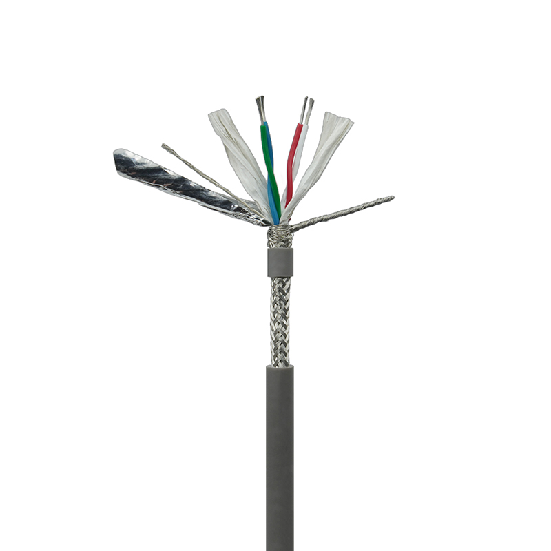
In practice, foil shields work well for static installations or very short flex zones. Under repeated bending, the thin aluminum layer cracks, leaving gaps that reduce coverage to below 60% within a few hundred thousand cycles. Copper braid shields with at least 85% coverage remain intact beyond 5 million cycles because each strand can slide slightly, distributing stress. For RS485 communication cables on linear slides, a braid-alone design is often sufficient. In a multi-axis robot with AC servo drives switching at 8 kHz, the combination shield becomes mandatory.
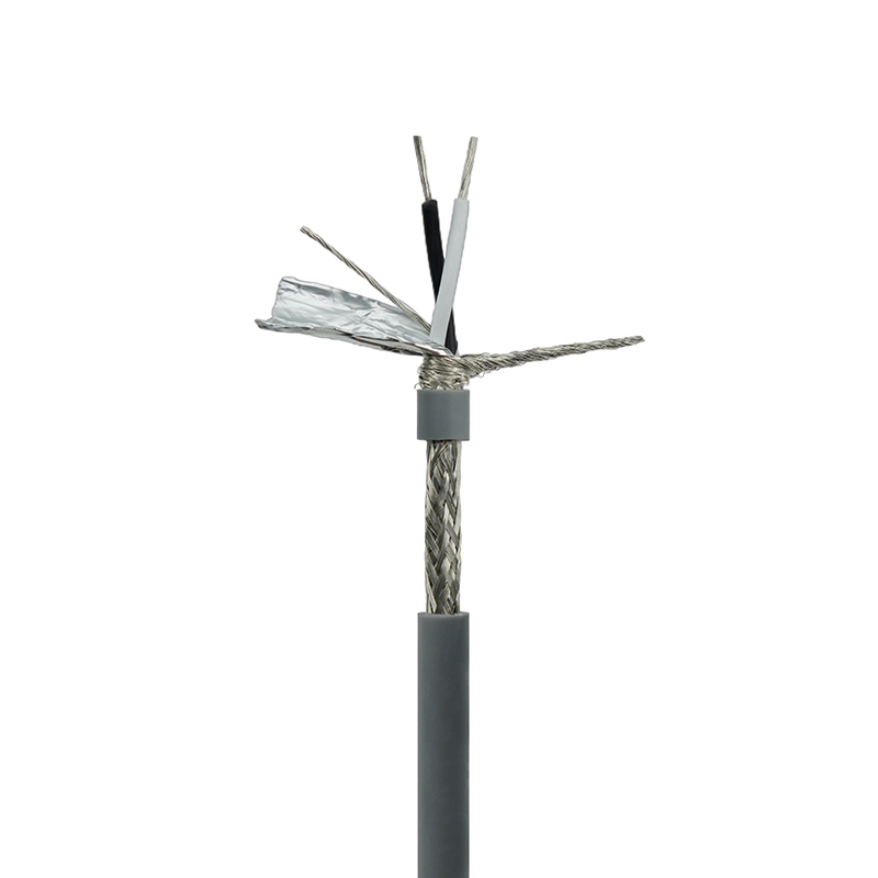
Installation details amplify the decision. A braid shield terminated with a full 360-degree EMC gland maintains its impedance through the connector. A foil shield pigtailed to a pin introduces a common-mode impedance spike that erodes high-frequency shielding effectiveness by 20 dB or more. These are not theoretical concerns — they are the difference between a machine that passes radiated emissions testing on the first try and one that requires repeated rework.
Jacket Material Deep Dive: PVC, PUR, and TPE
The outer jacket is the first line of defense against cutting oils, coolant sprays, and abrasive drag chain surfaces. It also determines the cable’s coefficient of friction, which directly impacts how smoothly the cable slides over itself in a carrier. Three materials dominate the market, and each has a distinct failure signature.
| Property | PVC | PUR | TPE |
|---|---|---|---|
| Abrasion resistance (Taber, cycles) | 1,000 – 2,000 | 5,000 – 10,000+ | 3,000 – 8,000 |
| Oil resistance (IRM 902, 70 °C) | Moderate | Excellent | Good to excellent |
| Low-temperature flexibility | -5 °C brittle | -40 °C flexible | -50 °C flexible |
| Hydrolysis resistance | Good | Moderate | Excellent |
| Relative cost index | 1.0 | 1.8 – 2.5 | 1.5 – 2.0 |
PVC remains the economic choice for enclosed machine tools where the ambient temperature stays above 0 °C and oil mist is light. Its low friction surface works well in cable tracks. The moment mineral oils, synthetic esters, or washdown chemicals are present, PVC softens and swells, increasing the cable’s diameter by 8–12%. That swelling forces the cable against the carrier walls, multiplying wear rates by a factor of three or more.
PUR jackets solve this with inherent chemical resistance. They also exhibit the highest cut and notch resistance, which matters when metal chips or weld spatter land on the cable. The trade-off is susceptibility to hydrolysis in hot, humid environments — above 60 °C and 80% relative humidity, standard PUR degrades within 18 to 24 months. TPE sidesteps both limitations: it resists hydrolysis, stays flexible below -40 °C, and handles most industrial oils. For outdoor automation systems or cold storage logistics, TPE is often the only viable jacket material.
Application-Specific Selection Matrix
No single cable design fits every dynamic environment. The matrix below maps four common applications to the recommended conductor, shield, and jacket combination. Use it as a starting point, then adjust based on your specific speed, temperature, and chemical exposure.
| Application | Conductor Type | Shielding | Jacket | Key Reason |
|---|---|---|---|---|
| Drag chain (horizontal) | Rope-lay, Class 6 fine strands | Braid or none | PUR | High cycles, abrasive track |
| Robot arm (torsional) | Bundle with low-lay length | Braid + foil | TPE | Twist resistance, EMI from drives |
| Crane & hoist | Extra-fine strands with steel support | Optional braid | PUR or TPE | Self-weight, long travels |
| Underwater / wet | Tinned fine strands | Foil or none | PUR or TPE | Hydrolysis, pressure |
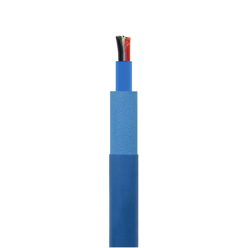
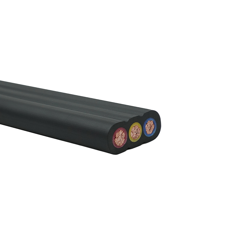
For cranes and hoists that run on flat cable tracks, the geometry changes from round to flat to prevent twisting. Crane flat cables with an integrated steel strain member eliminate the corkscrew effect that plagues round cables under vertical suspension. The flat profile also stacks cleanly in the cable basket, reducing chafing by distributing contact pressure over a wider surface.
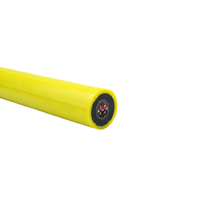
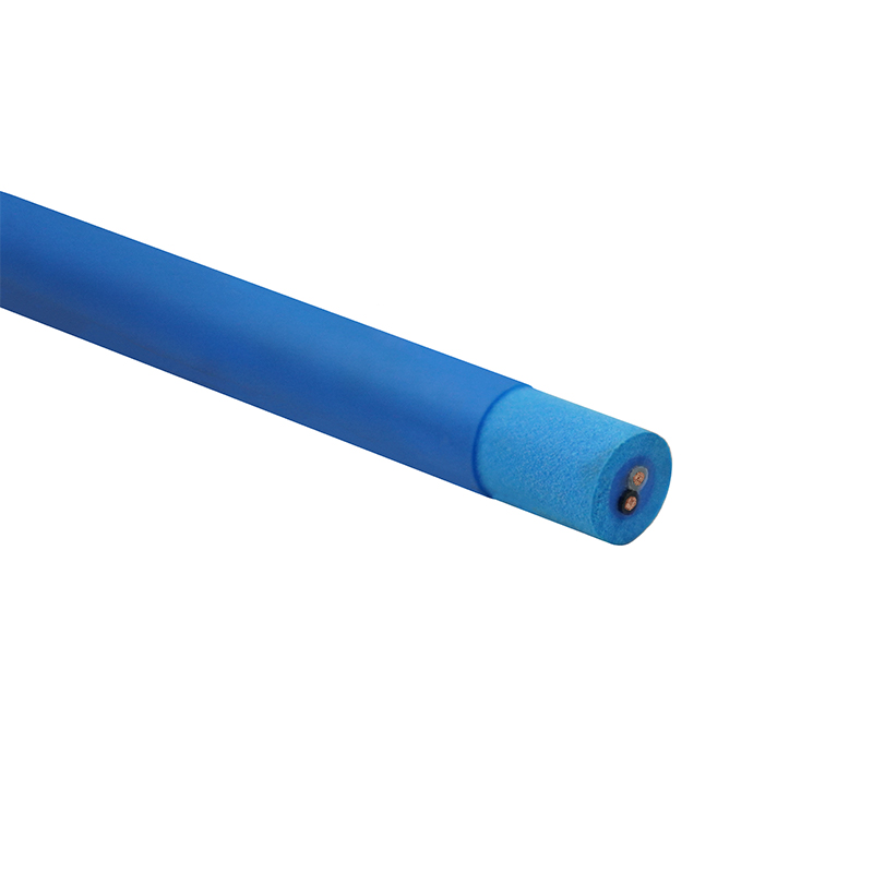
Underwater robots introduce a different challenge. Here the jacket must resist water absorption and micro-cracking under cyclic pressure. PUR formulations with hydrolysis stabilizers or TPE jackets dominate. Buoyancy also matters — a slight positive buoyancy cable reduces the load on the tether management system. Specialized buoyant cables for underwater robots combine these properties into a single design, eliminating the need for external flotation modules.
The Role of Certifications (UL, CE) in Cable Selection
A cable datasheet that lists “flex cycles: 5 million” without citing the test standard is offering an opinion, not a specification. UL 1277 defines the test apparatus, the bending radius, the travel speed, and the failure criteria. A cable that passes UL 1277 has demonstrated a minimum of 2 million cycles under controlled conditions while maintaining electrical integrity. The same logic applies in Europe with HD 22.13 and EN 50525-2-51 for PVC and rubber flexible cables.
CE marking on a continuous flex cable does not automatically mean it meets flex-life requirements. CE is a declaration of conformity to relevant EU directives, primarily the Low Voltage Directive. The flex performance is separately validated through harmonized standards. Buyers should request the specific standard number and test report. Similarly, a UL Listed mark (vs. merely UL Recognized components) indicates that the finished cable assembly — not just the raw materials — has passed the flexing test.
For cables destined for North American machinery, UL 2464 and UL 2586 are the most common style numbers encountered on continuous flex cables. The existence of a UL file number allows the cable to be accepted by local electrical inspectors without additional field evaluation. That single paperwork detail can shave two to four weeks off a machine’s commissioning timeline, a factor that plant managers weigh heavily when total project cost is calculated.
Total Cost of Ownership: Why Cheap Cables Cost More
Consider a packaging machine with 20 cable carriers, each housing three cables. A standard flex cable priced at $2.10 per foot lasts 12 months in operation. A continuous flex cable priced at $4.80 per foot lasts 48 months. The initial cable bill difference is $3,240 versus $7,380. Over a four-year cycle, the standard option requires replacement three times, bringing the total cable cost to $9,720 — already higher. But the real expense is downtime.
| Cost Category | Standard Flex (1-year life) | Continuous Flex (4-year life) |
|---|---|---|
| Cable material (4 years) | $9,720 | $7,380 |
| Labor for replacement (3 events) | $6,000 | $0 |
| Lost production (8 hours per event) | $48,000 | $0 |
| Total 4-year cost | $63,720 | $7,380 |
A cable that costs twice as much upfront can reduce total lifecycle cost by nearly 90% once labor and lost output are included. This calculation assumes a single shift operation. For a three-shift automotive line producing $1,800 worth of components per minute, the downtime cost dwarfs all other numbers, making the premium for certified continuous flex cable effectively free.
The hidden variable is collateral damage. A cable that fails catastrophically in a drag chain can snag and rip out adjacent pneumatic hoses, fiber optic links, and sensor cables. The eight-hour repair window can easily stretch to sixteen when secondary damage is involved. Plant maintenance teams learn this lesson once; after that, they insist on continuous flex cable by name.
When Standard Isn't Enough: Exploring Custom Cable Solutions
Standard product lines cover perhaps 80% of automation applications. The remaining 20% — the ones that generate the most field failures — involve combinations of travel distance, bend radius, ambient temperature, and chemical exposure that no off-the-shelf cable can survive. Custom cable engineering closes this gap.
The customization process typically follows four steps: a joint application review to map all mechanical and environmental constraints, rapid prototyping of the conductor-stranding and jacket compound, accelerated life testing on a flexing machine, and finally, production of a batch that includes the exact lay length, filler materials, and shield coverage proven to work. The entire cycle can take as little as six weeks for a skilled manufacturer with in-house stranding and extrusion.
Common triggers for going custom include bend radii below 5x cable diameter, travel speeds above 10 m/s, simultaneous exposure to -30 °C and oil splash, or the need to combine power, signal, and Ethernet with a single overall shield. In such cases, a custom-engineered cable is not an upgrade — it is the only option that keeps the machine running past the warranty period.
- Ultra-tight bend radius (<5x diameter)
- Extreme speed (above 8 m/s with acceleration > 20 m/s²)
- Simultaneous oil, cold, and mechanical impact
- Hybrid cables: power + Cat6a + encoder feedback in one jacket