 EN
EN
 English
 русский
 Español
Thermocouple Extension Cable: How to Select the Correct Type, Gauge & Insulation
 Industry News
Content
- 1 What is a Thermocouple Extension Cable?
- 2 Thermocouple Grade vs. Extension Grade: What’s the Difference?
- 3 Compensating Cable: A Cost-Driven Alternative
- 4 How to Choose the Right Insulation Material for Your Environment
- 5 Understanding Shielding: Foil vs. Braid vs. Overall Shield
- 6 Wire Gauge (AWG) and Signal Transmission Distance
- 7 Common Thermocouple Types and Their Matching Extension Cables
- 8 Installation Best Practices for Accurate Readings
What is a Thermocouple Extension Cable?
A 5-degree measurement error in a glass annealing furnace can scrap an entire batch. More often than not, the culprit isn't the sensor but the cable bridging the gap between the thermocouple and the control room. That cable is the thermocouple extension cable, and it's responsible for carrying the tiny millivolt signal without corrupting it.
Extension cable uses conductors made from alloys that closely match the thermoelectric properties of the thermocouple. It lets you place the instrument hundreds of feet away without introducing a secondary junction that would distort readings. Unlike ordinary copper wire, which would create parasitic voltages at every connection point, a proper extension cable keeps the signal true across the full temperature compensation loop. The key insight: the cable doesn't measure temperature; it faithfully transports the voltage that a thermocouple generates, which is why alloy selection is non-negotiable.
Thermocouple Grade vs. Extension Grade: What’s the Difference?
All thermocouple wiring falls into two grades: thermocouple grade and extension grade. The difference comes down to alloy purity, accuracy tolerance, and cost. Thermocouple-grade wire is fabricated from the same high-purity alloys as the sensor itself, so it can withstand the full measurement temperature. Extension-grade wire uses alloys with a slightly relaxed composition that matches the thermocouple’s output only over a limited ambient range, typically below 200°C (392°F).
When you run cable inside a furnace, you need thermocouple grade. When you're extending the signal from a junction box in a climate-controlled cabinet to a PLC, extension grade works perfectly and saves you 30 to 50 percent in material cost. Using extension-grade wire where thermocouple-grade is required causes drift and accuracy loss of ±2.2°C or more compared to ±1.1°C for premium thermocouple-grade circuits.
| Parameter | Thermocouple Grade | Extension Grade |
|---|---|---|
| Alloy Purity | High-purity thermoelement alloys | Matching alloys with relaxed tolerances |
| Temperature Limit | Full sensor range (e.g., up to 1260°C for Type K) | Typically 0 to 200°C ambient |
| Accuracy (standard limits) | ±1.1°C or ±0.4% | ±2.2°C or ±0.75% |
| Cost Ratio | 100% | 50–70% of thermocouple-grade price |
| Typical Use | Probe leads, furnace wiring | Junction box-to-instrument runs |
The decision rarely requires guesswork. If the cable will ever see temperatures beyond 200°C or becomes an integral part of the sensor circuit inside the thermal zone, grade up. If you are simply linking a remote head-mounted transmitter to a data logger across a plant floor, extension grade is the economical, electrically sound choice.
Compensating Cable: A Cost-Driven Alternative
Where extension-grade cable uses alloys that mirror the thermocouple’s exact composition, compensating cable relies on entirely different, cheaper alloys that mimic the emf output only over a narrow temperature window. This approach cuts material expense by another 20 to 40 percent, but at a cost: a compensating cable for Type K, such as KC, cannot be connected directly to the thermocouple in a high-temperature zone, and its effective ambient range usually ends below 100°C.
Compensating cable fills a niche. It is appropriate for short, climate-controlled indoor runs where accuracy is secondary and budget is primary. For example, a FEP-insulated KC compensating cable works well in laboratory patch panels, but you would not use it on a forging press. In contrast, a PVC-insulated KX extension cable carries exactly the same emf profile as the sensor, giving you full accuracy even over hundreds of feet. The rule is simple: extension cable for precision, compensating cable for non-critical monitoring where every dollar counts.
How to Choose the Right Insulation Material for Your Environment
Conductor alloys steer the signal; insulation keeps it alive. The insulation jacket must resist temperature, moisture, oil, abrasion, and sometimes chemical attack. Selecting the wrong material can lead to brittle cracking at -40°C or melting under a nearby steam line.
| Material | Continuous Temp. Range | Oil/Chemical Resistance | Flexibility | Best For |
|---|---|---|---|---|
| PVC | -40 to 105°C | Fair | Good | Indoor, light-duty, low-cost runs |
| FEP | -60 to 200°C | Excellent | Fair | Corrosive chemical plants, high humidity |
| PFA | -60 to 260°C | Excellent | Fair | High-temperature aggressive environments |
| Fiberglass | -60 to 480°C (dry) | Poor (absorbs moisture) | Fair | Ovens, heaters, high-temp test cells |
| PUR (Polyurethane) | -40 to 125°C | Excellent | Excellent | Drag chains, robotics, moving machinery |
For most indoor panel wiring, PVC gets the job done at the lowest cost. In a wet, oil-soaked paper mill, FEP’s chemical inertness prevents swelling and signal leakage. When the cable snakes through a cable carrier on a gantry robot, PUR’s continuous-flex drag chain cable construction withstands millions of bending cycles without shattering. Fiberglass jackets excel in furnace wiring but demand careful handling because they absorb humidity and lose dielectric strength when wet. Always derate the cable’s temperature rating when both heat and moisture are present.
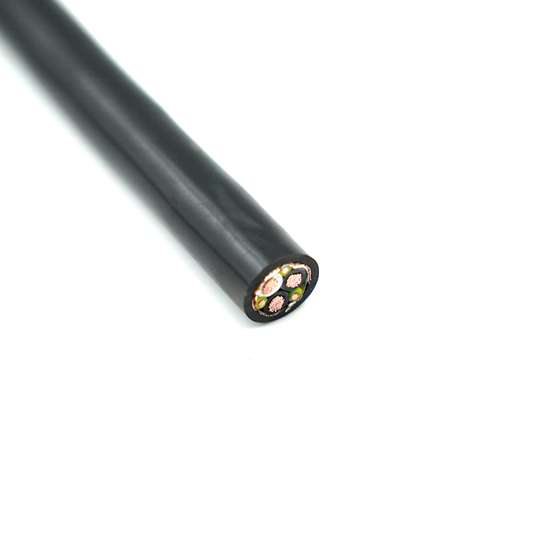
Understanding Shielding: Foil vs. Braid vs. Overall Shield
A thermocouple’s output is a low-level direct voltage, often just a few millivolts. In a plant with variable frequency drives, large motors, and switchgear, stray electromagnetic fields can superimpose AC noise on that signal, producing random ±3°C swings on the display. Shielding blocks that interference before it reaches the controller.
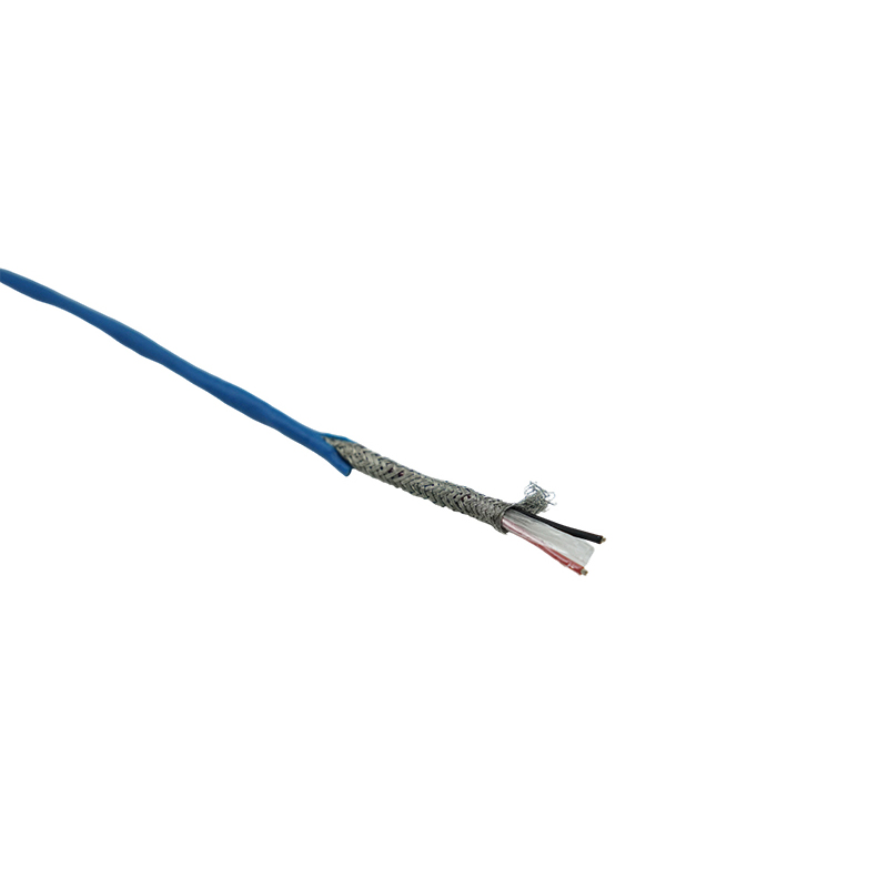
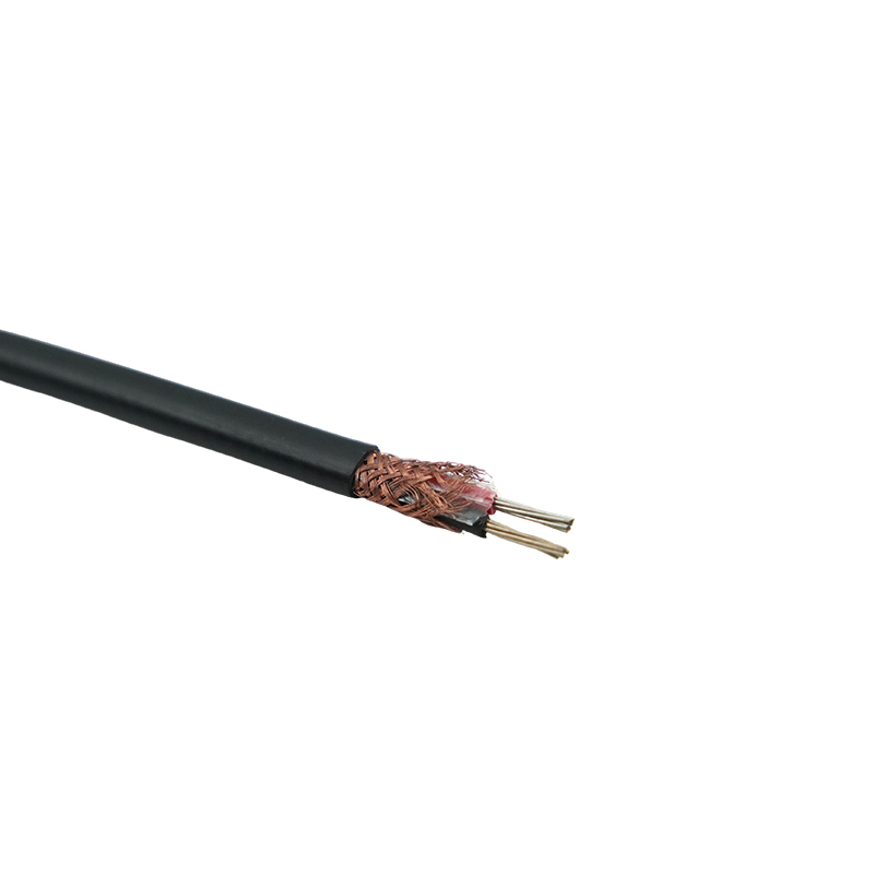
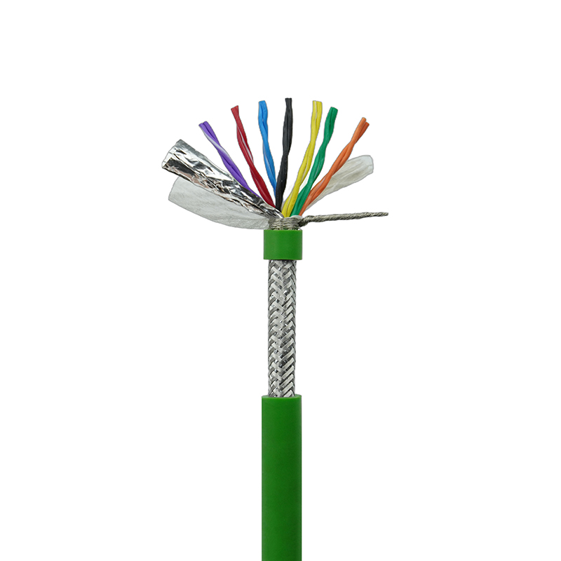
Three shielding strategies dominate. Aluminum/polyester foil with a drain wire provides 100% coverage and works well against electrostatic noise, but it is fragile and can tear during flexing. Tinned copper braid offers 70–95% coverage with low DC resistance and excellent mechanical strength, making it the go-to for high-flex and heavy-vibration installations. An overall shield protects all pairs inside a multi-pair cable from external noise, while individual pair shields prevent crosstalk between channels when you carry multiple thermocouple signals in one jacket.
In a VFD-heavy panel, a combination foil-plus-braid shield is the most reliable defense, a technique similar to the braided shielding methods used in purpose-built VFD cable. For single-point, short-distance connections, foil with drain wire is sufficient. When routing extension cables near power conductors, always maintain at least 12 inches of separation, and cross at right angles if you must intersect.
Wire Gauge (AWG) and Signal Transmission Distance
The loop resistance of the extension cable adds to the total circuit resistance and can attenuate the thermocouple’s signal. Thin conductors (24 AWG) introduce more resistance per foot than thick ones (20 AWG), and excessive resistance causes the instrument to misread the actual voltage. This becomes critical in long runs where the cable acts as a voltage divider.
| AWG | Resistance (Ω/1000 ft) | Max Recommended Distance (ft)* |
|---|---|---|
| 20 | ~10.4 | 1000 |
| 22 | ~16.5 | 700 |
| 24 | ~26.2 | 400 |
*Assumes a 100 Ω maximum loop resistance budget for typical thermocouple input modules.
These distances are not hard limits but rather design baselines. Heavier gauge wire reduces resistance and extends reach, but also adds weight and cost. For a 100-ft run inside a control cabinet, 24 AWG is perfectly fine. For a 900-ft span between a kiln and the control room, 20 AWG keeps the signal above the noise floor. Always check the instrument’s input impedance specification; modern high-impedance digital transmitters tolerate higher loop resistance and can double the usable distance compared to legacy analog meters.
Common Thermocouple Types and Their Matching Extension Cables
Every thermocouple type requires a specific extension cable designation; mixing types creates an additional thermoelectric junction at the connection point, offsetting readings by tens of degrees. The letter codes are straightforward: for a Type K thermocouple, you need KX extension cable; for Type J, JX, and so on.
- Type K (Chromel/Alumel): KX extension cable. Yellow jacket per ANSI. Ambient range to 200°C. Avoid reducing atmospheres.
- Type J (Iron/Constantan): JX extension cable. Black overall jacket. The iron positive leg rusts in wet conditions; use indoors.
- Type T (Copper/Constantan): TX extension cable. Blue jacket. Ideal for sub-zero and cryogenic measuring up to 350°C.
- Type E (Chromel/Constantan): EX extension cable. Purple jacket. Highest emf output per degree, excellent for low-temperature differential measurements.
- Type N (Nicrosil/Nisil): NX extension cable. Orange jacket. Better high-temperature stability than Type K in oxidizing environments.
Compensating alloys (KC, JCA, etc.) have their own color codes and are only rated for limited ambient temperatures, typically below 100°C. Using a KC compensating cable on a K-type sensor does work for short indoor hops but introduces a few more microvolts of error per degree than an equivalent KX circuit. When you audit an installation and find random jumps, mismatched cable is one of the first things to inspect.
Installation Best Practices for Accurate Readings
Even the right cable performs poorly if installed like power wiring. The following practices shield your signal from the moment the cable leaves the junction box.
- Maintain polarity on every connection: the magnetic (negative) leg must match all the way to the instrument; reversed connections will subtract ambient temperature instead of adding it.
- Keep extension cables at least 12–18 inches from AC power lines, VFD motor leads, and fluorescent ballasts.
- Avoid intermediate terminal blocks and connectors where the temperature difference between terminals can create unwanted junctions; use thermocouple-specific terminal blocks with matched alloys.
- Never install extension cable in areas exceeding its rated ambient temperature; a PVC jacket in a 120°C environment melts and exposes the conductors.
- Secure the cable with wide-radius clamps, never with metal staples that can pierce the jacket and short the shield to ground at uncontrolled points.
- In high-vibration zones, use stranded rather than solid conductors and choose a PUR or braided jacket to prevent work hardening and conductor fracture.
- Label both ends clearly with the thermocouple type and cable grade; this avoids future cross-connection during maintenance.
Verify every run with a handheld calibrator after pulling the cable. A simple loop check that injects a known voltage confirms the circuit is intact, correctly polarized, and free of ground faults before you trust it with process control.
")
")


