 EN
EN
 English
 русский
 Español
Cable Braid Selection Guide: Copper vs. Stainless Steel for EMI Shielding
 Industry News
Content
- 1 What Is Cable Braid and Why Does It Matter?
- 2 Braid Materials Compared: Copper, Stainless Steel, and Aluminum
- 3 Key Technical Parameters: Braid Coverage, Angle, and Density
- 4 Application-Specific Braid Selection: Drag Chain, Elevator, Underwater & More
- 5 Compliance & Standards: UL, CE, and CCC Requirements for Braided Shields
- 6 Installation Best Practices: Stripping, Terminating, and Grounding Braided Cables
- 7 Cost vs. Performance: When to Choose a Simpler Shield
What Is Cable Braid and Why Does It Matter?
A cable braid can block up to 95% of electromagnetic interference when coverage exceeds 90%. That single fact drives its role in industrial cable design—without a properly selected braid, control signals degrade, sensors fail, and equipment halts. Braid is not merely a cosmetic layer; it is a precision-engineered metallic shield.
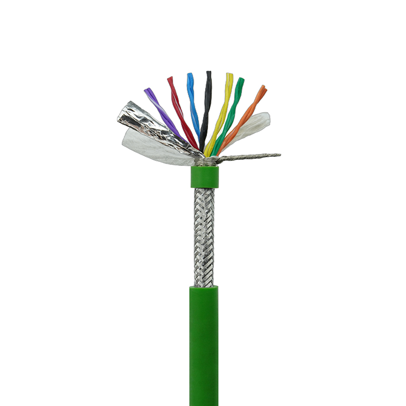
At its core, a cable braid is a tubular mesh woven from fine metal wires—usually copper, stainless steel, or aluminum—that wraps around a cable core. The weaving pattern creates a flexible, conductive barrier that performs three essential functions simultaneously. First, it suppresses electromagnetic interference (EMI) by reflecting and absorbing radiated noise. Second, it provides mechanical protection against abrasion and crush loads, often reinforcing the cable’s tensile strength. Third, it establishes a reliable ground path, diverting fault currents safely to earth.
These functions are not interchangeable. A braid optimized for mechanical toughness may sacrifice some shielding effectiveness, while a design targeting high-frequency EMI reduction demands precise coverage calculations. Engineers who ignore these trade-offs end up with cables that pass lab tests but fail in the field. Understanding the underlying physics—and the numbers that govern it—is the starting point for every successful specification.
Braid Materials Compared: Copper, Stainless Steel, and Aluminum
Three metals dominate cable braid production, and choosing among them comes down to four performance vectors: conductivity, tensile strength, corrosion resistance, and cost. Copper stands as the benchmark, but it is not universal. Stainless steel enters when abrasion or pull forces dominate. Aluminum offers a lightweight, budget-friendly alternative for less demanding environments.
The table below distills decades of field data into a single comparison. Conductivity is measured in percent IACS (International Annealed Copper Standard), tensile strength in megapascals, and relative cost against aluminum as the baseline.
| Material | Conductivity (% IACS) | Tensile Strength (MPa) | Corrosion Resistance | Relative Cost |
|---|---|---|---|---|
| Copper | 100 | 200 | Moderate (oxidizes, not for marine) | 2x |
| Stainless Steel | 2 | 500 | Excellent (resists salt spray, acids) | 3x |
| Aluminum | 61 | 90 | Good (forms protective oxide) | 1x |
Copper’s conductivity makes it the first choice for EMI-critical environments, especially where signal integrity matters. Stainless steel, despite its poor conductivity, provides unmatched mechanical protection and is standard in floating cable applications exposed to seawater or aggressive chemicals. Aluminum sits in the middle—light, conductive enough for many industrial control signals, and significantly cheaper, though it demands careful termination to avoid galvanic corrosion against copper connectors.
Key Technical Parameters: Braid Coverage, Angle, and Density
Three engineering variables determine how a braid performs: coverage, braid angle, and strand density. None can be optimized in isolation; improving one often degrades another. Coverage—the percentage of the cable core surface physically obscured by metallic wires—is the headline number most spec sheets quote, but it tells only part of the story.
Coverage is calculated from the wire diameter, number of carriers, picks per inch, and cable diameter. The standard formula is: Coverage (%) = (2 × d × N × P) / (π × D) × 100, where d is the single-wire diameter, N the number of carriers, P the picks per unit length, and D the braid inner diameter. A 90% coverage rating typically delivers 10–15 dB better shielding than an 85% rating above 30 MHz—a margin that often separates a compliant installation from a failure in an industrial plant.
Braid angle, measured between the wire and the cable axis, controls the balance between flexibility and shielding. A 30° angle yields maximum flex life but reduces coverage edges. A 60° angle maximizes high-frequency attenuation yet sharply limits bend cycles. Most industrial cables use a 45° angle, which provides the best compromise for dynamic applications like drag chains. Density—the number of wire crossings per unit length—directly influences both coverage and cable stiffness. Dense braids increase coverage but raise cost and reduce flexibility, so designers must match density to the expected number of bending cycles.
Application-Specific Braid Selection: Drag Chain, Elevator, Underwater & More
Context dictates every braid choice. A cable hauling data inside a robotic arm faces different stresses than one hanging in an elevator shaft or one submerged 100 meters below a research vessel. The following scenarios illustrate how braid material, coverage, and angle shift across real-world industrial uses.
Drag Chain and Moving Gantry Systems
Cables in drag chains routinely exceed 10 million bending cycles. Here, braid must be exceptionally flexible and resists work-hardening. High-coverage tinned copper braid with a 45° angle survives these conditions while protecting encoder and feedback signals. Standard aluminum or stainless steel braids would crack prematurely. For new installations, our drag chain cables integrate this exact braid configuration, tested to withstand the repetitive motion that destroys generic shielded cable.
Elevator Traveling Cables
Elevator flat cables combine tensile load-bearing with signal transmission in a confined shaft. The braid here serves dual duty—it shields the communication pairs from VFD noise and reinforces the cable mechanically. A copper braid with supplemental steel wire strands delivers the necessary tensile strength while maintaining coverage above 85%. The design found in elevator traveling flat cables proves how braid and load-bearing elements can coexist without compromising either function.
Underwater and Marine Environments
Subsea cables confront constant corrosion risk. Stainless steel braid becomes mandatory here, not for its conductivity but for its resistance to saltwater pitting and biofouling. Even moderate coverage of 80% with a 316L stainless braid extends cable life far beyond any copper-based alternative. In ROV and sonar deployments, the braid also acts as an effective low-impedance ground, despite the lower conductivity, because the short cable runs keep voltage drop negligible.
Compliance & Standards: UL, CE, and CCC Requirements for Braided Shields
Regulatory frameworks do not treat braid as optional. UL 2464, for example, mandates minimum coverage thresholds and conductivity limits for cables installed in North American control panels. CE’s EMC Directive references EN 50289 for shielding attenuation, while China’s CCC certification derives from GB/T standards that often echo IEC methodologies. Understanding these requirements before specifying a cable avoids costly redesigns.
| Standard | Critical Braid Requirements | Primary Market |
|---|---|---|
| UL 2464 | Minimum 85% coverage; copper or tinned copper; DC resistance limits | North America |
| CE (EN 50289) | Transfer impedance test; 90% coverage typical for Cat 5e and above | European Union |
| CCC (GB/T 9330) | Coverage not less than 80%; copper braid required for power+control hybrid cables | China |
North American UL requirements focus on fire safety and electrical performance, so braid resistance values are strictly capped. The European approach leans toward EMC performance, mandating transfer impedance measurements that validate overall shield effectiveness rather than just coverage percentage. CCC overlaps both, adding national material mandates. When exporting a machine globally, a single braid design that meets the strictest of these standards—typically UL 2464 with 90% tinned copper—often proves the most economical path through compliance.
Installation Best Practices: Stripping, Terminating, and Grounding Braided Cables
A perfectly specified braid fails instantly if installed incorrectly. The most common field errors involve excessive stripping, inadequate strain relief, and improper grounding topology. Following a controlled termination sequence mitigates these risks.
- Strip: Remove the outer jacket to expose 10–15 mm of braid, depending on connector type. Use a rotary strip tool set to the jacket thickness to avoid nicking the braid wires.
- Fold back: Carefully fold the braid back over the jacket. Do not twist excessively; a single, even fold prevents wire breakage.
- Attach ferrule or clamp: Slide a dimensionally matched tinned copper ferrule over the folded braid and crimp using a controlled-cycle tool. Target crimp force consistent with the ferrule manufacturer’s data—typically 10–15 Nm for cable diameters 6–12 mm.
- Grounding method: For frequencies below 1 MHz, a single-point ground at the source end avoids ground loops. For frequencies above 10 MHz, a 360-degree shield termination at both ends reduces radiated emissions. Hybrid approaches using capacitive grounding at one end can balance noise and safety.
- Verify: Measure DC resistance from braid to connector body—values above 10 milliohms indicate a compromised crimp or contamination.
These steps, when combined with proper strain relief, ensure the braid performs as the datasheet promises. Skipping even one step degrades the shield’s effectiveness by up to 20 dB in field measurements.
Cost vs. Performance: When to Choose a Simpler Shield
Not every cable requires a full copper braid. In fact, over-specifying is a common budget drain in low-frequency industrial automation. A simple decision matrix, based on frequency, environment, and flex cycles, can steer engineers toward the right economic choice.
For sensor circuits operating below 1 MHz in dry, fixed installations, a spiral or aluminum foil shield with an overall drain wire typically delivers sufficient EMI rejection at half the cost of a copper braid. Once frequencies climb above 30 MHz—as in encoder cables or VFD motor leads—an aluminum foil shield alone becomes inadequate, and a copper braid or combination foil/braid shield becomes necessary. High-flex environments further restrict foil-only designs; a braid is mandatory if the cable experiences over 1 million bend cycles.
The up-front material cost difference of 2–3x between aluminum and copper braid on a small-diameter cable may seem trivial per meter, but multiplying by thousands of meters in a plant-wide installation justifies the analysis. Selecting a braid only where physics demands it frees budget for higher-quality connectors and terminations, which often yield greater system-level EMC improvements than an extra 5% coverage.


