 EN
EN
 English
 русский
 Español
1/0 Welding Cable Ampacity: Ratings, Duty Cycle, and Real-World Selection Guide
 2026.08.19
 Industry News
Content
A maintenance supervisor needs a new set of leads for a 300 A MIG welder. The 1/0 AWG welding cable on the storage drum looks like the right choice, but the ampacity chart from the supplier lists 150 A next to the 1/0 row while a different chart shows 300 A for the same cable. Which number is correct? Both are, under different conditions. A 1/0 copper welding cable is rated around 150 A for continuous duty at a 60 °C conductor temperature, yet it carries 250-300 A in normal welding service because a welder never draws rated current without interruption. The actual question is not whether 1/0 can handle the amperage, but how long the current flows, how often, and over what total cable length.
What “1/0 Welding Cable Ampacity” Actually Means
Ampacity is the maximum current a conductor can carry without exceeding the temperature rating of its insulation. Overheating a cable ruins the jacket, accelerates conductor oxidation, and creates a fire risk in a few unattended minutes. For welding cable, published ampacity values fall into two broad groups: continuous-duty ratings intended for portable power cable used like a fixed feeder, and intermittent-duty ratings that describe real welding service.
The 1/0 AWG designation refers to the conductor size, about 53.5 mm² of copper in standard stranded construction. Welding cable is built differently from ordinary building wire. The conductor uses fine copper strands, typically Class K or Class M stranding, so it bends repeatedly in torch handles and survives being dragged over concrete and sharp metal. The insulation is a thick rubber compound, usually neoprene, EPDM, or a thermoset blend, rather than a thin PVC layer. Because the insulation temperature rating defines the ampacity, manufacturers publish values at 60 °C, 75 °C, and 90 °C conductor temperatures, and those values differ by more than 20%.
1/0 Welding Cable Ampacity at a Glance
The table below summarizes representative published ampacity values for 1/0 AWG copper welding cable under different rating bases. Values vary slightly between manufacturers, so the actual data sheet for the cable you intend to buy should always be the final reference.
| Rating basis | Typical ampacity for 1/0 AWG copper |
|---|---|
| Continuous duty, 60 °C conductor temperature (600 V in-line applications) | 150 A |
| Continuous duty, 75 °C conductor temperature | 170-175 A |
| Continuous duty, 90 °C conductor temperature | 195-205 A |
| Welding service, 60% duty cycle | 250-300 A |
| Welding service, light intermittent duty | 350-400 A |
The 150 A figure almost always comes from 600 V in-line portable cable tables that assume continuous operation in a 40 °C ambient. The 250-300 A figures come from welding-duty curves that assume a defined duty cycle. Neither value is wrong; they answer different questions, and a buyer who does not recognize the distinction will either under-specify the cable or pay for a heavier size than the job needs.
Why Duty Cycle Matters More Than a Single Number
Duty cycle is the percentage of a ten-minute period during which the welding machine actually delivers current. A power source rated 300 A at 60% duty cycle runs the arc for six minutes and idles for four. The cable sees the same pattern, so its average current is about 180 A, not 300 A, and the conductor temperature stays inside the insulation class. That is why a 1/0 lead works on machines rated well above its continuous-duty ampacity.
Different processes change the calculation. Stick welding and heavy MIG welding run longer arc times, so the effective duty cycle is higher. TIG welding usually runs at lower average current. Automated welding cells, by contrast, can sustain current for long stretches without a pause, which pushes the cable toward its continuous rating.
Problems appear when the duty cycle estimate is wrong. High-current CV welding, hot summer shops, and cables coiled on the floor with heat trapped in the center all reduce the time available for cooling. If an operator cannot keep a hand on the jacket after sustained work, the cable is running too hot; the correct response is to reduce the load or move to a larger gauge.
Voltage Drop and Cable Length Set the Real Limit
Thermal ampacity is only half of the selection process. A 1/0 copper conductor has a resistance of about 0.098 ohm per 1000 ft at 25 °C. A 300 A welding current through a 100 ft electrode lead plus a 100 ft work lead, a 200 ft total loop, drops about 5.9 V. Against a 36-40 V arc, that is more than 15% of the arc voltage. The result is an unstable arc, poor penetration, spatter, and inconsistent wire feed.
Long leads create a second problem: welding machines regulate voltage at their output terminals, so a cable that drops significant voltage forces the operator to turn the machine up, which increases current and heats the cable even more. The cable and the machine end up working against each other.
A practical guideline: 1/0 keeps voltage drop acceptable up to roughly 100-150 ft of total loop at 250-300 A. Beyond that distance, move up to 2/0 or 3/0. In long-run installations, cable length forces a size change even when thermal ampacity alone would allow 1/0.
Ambient Temperature, Jacket Compound, and Flexibility
Continuous-duty portable cable tables assume a 40 °C ambient. A lead routed across a hot factory roof, through an unventilated enclosure, or across sun-heated asphalt must be derated. The correction works both ways: cooler environments allow higher loading, but the safe direction is to derate whenever the site is hotter than the table assumption.
The jacket compound controls how much physical punishment the cable survives. Rubber-based compounds resist oil, abrasion, moisture, and UV exposure, and good grades stay flexible down to -40 °C or lower while holding a continuous rating up to 90 °C or higher. A 90 °C-rated jacket offers genuine headroom over a 60 °C-rated equivalent when the lead operates near capacity.
Flexibility is a daily usability issue that ampacity tables never show. A 1/0 conductor with fine stranding and a supple jacket flexes easily in the torch handle and stays manageable when dragged around a workshop. If the same cable is destined for a drag chain, robotic arm, or reeling drum, the construction requirements are entirely different, and a supplier experienced in motion-flex cable design should make the recommendation.
Choosing a 1/0 Welding Cable with Confidence
Cable selection comes down to a sequence that ignores marketing numbers and matches the actual job:
- Identify the maximum output current the welding process will use.
- Estimate the true duty cycle from the machine specification and the operator's working pattern.
- Measure the total loop length: electrode lead plus work lead, not just one side.
- Check the ambient temperature and the installation route for heat sources.
- Compare the result with the welding-duty ampacity of 1/0, and move up a size if the application approaches continuous duty.
Most manual welding jobs land inside the 1/0 envelope at 250-300 A. Automated, long-cycle, or very hot installations often do not, and choosing 2/0 is the correct move when the conditions demand it.
For a complete comparison of sizes from #2 through 4/0, including how the AWG scale works and how machine ratings map to lead sizes, see our welding lead sizes and ampacity selection guide.
When the specification is ready, the physical construction matters as much as the cross-section. A high-strength rubber welding cable with fine copper stranding and a tough but flexible jacket is the type of product most shops rely on in the 1/0 class. A specialty cable manufacturer can confirm the documented ampacity for the exact insulation compound and support the selection with test data rather than a generic chart.
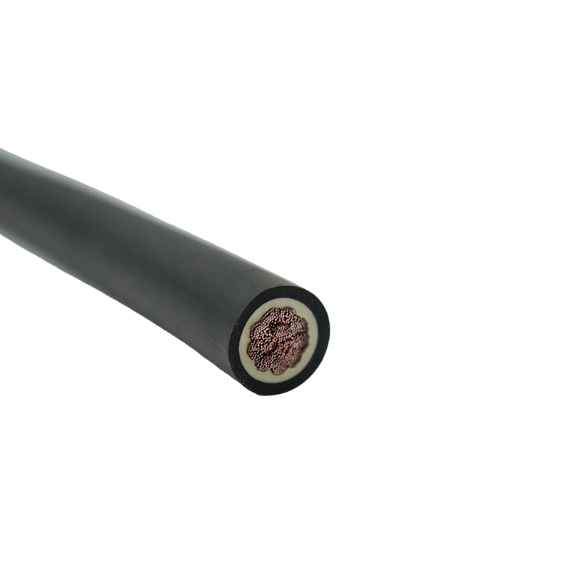 YH High-Strength Rubber Welding Cable Suppliers, Wholesale Company - Jiangsu JunAs YH High-Strength Rubber Welding Cable Suppliers and Company in China, Junshuai offer Wholesale High-Strength Rubber Welding Cable onli...View Product →