 EN
EN
 English
 русский
 Español
Wire Size & Ampacity: How to Read Ampacity Charts and Choose the Right Cable
 2026.08.14
 Industry News
Content
- 1 Ampacity Is a Temperature Limit, Not a Conductor Property
- 2 How to Read a Wire Size and Ampacity Chart
- 3 Five Variables That Change the Ampacity of a Given Gauge
- 4 A Worked Example: Sizing Copper Wire for a 30 A Load
- 5 Industrial Cable Selection: Where Ampacity Gets Complicated
- 6 What to Specify When You Buy Cable
A maintenance engineer is rewiring a 7.5 kW motor on a packaging line. The motor draws 15.5 A at full load, and someone suggests pulling 14 AWG copper to save cost. That works in a clean, cool, single-cable run, but this cable has to travel 60 meters through a steel conduit shared with three other energized conductors, in a plant that regularly sits above 40°C in summer. Under those conditions, 14 AWG is marginal at best and, depending on insulation rating, not code-compliant.
Wire size and ampacity therefore have to be read together, not treated as a single number on a chart. The gauge defines the physical size of the conductor; the ampacity defines how much current it can carry safely in a specific installation. Here is what ampacity depends on, how to read ampacity charts without fooling yourself, and what to specify when you buy cable for a real circuit.
Ampacity Is a Temperature Limit, Not a Conductor Property
Ampacity is the maximum current, in amperes, that a conductor can carry continuously under the conditions of use without exceeding its temperature rating. Two parts of that definition get overlooked. "Continuously" means hour after hour, not just for the few seconds of a motor start. "Under the conditions of use" means ambient temperature, grouping, enclosure, and termination ratings all participate in the answer.
The physics is simple: heat generated in the conductor is proportional to the square of the current (I2R loss). Copper and aluminum tolerate that heat, but the insulation around them does not. PVC insulation is typically rated 60°C or 75°C, XLPE 90°C, and silicone rubber 150°C or 180°C in specialized cables. When the insulation reaches its rated temperature, the conductor has reached its ampacity.
How to Read a Wire Size and Ampacity Chart
Wire sizes in North America follow the American Wire Gauge (AWG) system, where a smaller number means a thicker conductor. Every three gauge steps approximately doubles or halves the cross-sectional area, so 10 AWG has roughly twice the area of 13 AWG.
Most ampacity charts for North American work are based on NEC Table 310.16, which lists allowable ampacities at three insulation temperature ratings: 60°C, 75°C, and 90°C. The same physical wire appears three times because the insulation, not the copper, sets the limit.
| AWG | 60°C (A) | 75°C (A) | 90°C (A) |
|---|---|---|---|
| 14 | 15* | 20* | 25* |
| 12 | 20* | 25* | 30* |
| 10 | 30* | 35* | 40* |
| 8 | 40 | 50 | 55 |
| 6 | 55 | 65 | 75 |
| 4 | 70 | 85 | 95 |
| 2 | 95 | 115 | 130 |
| 1 | 110 | 130 | 145 |
| 1/0 | 125 | 150 | 170 |
| 2/0 | 145 | 175 | 195 |
| 3/0 | 165 | 200 | 225 |
| 4/0 | 195 | 230 | 260 |
The asterisks mark the small-conductor rule in NEC 240.4(D): 14 AWG is limited to a 15 A overcurrent device, 12 AWG to 20 A, and 10 AWG to 30 A regardless of insulation rating. A 12 AWG conductor with 90°C insulation can carry 30 A per the table, but code still treats it as a 20 A conductor for most circuits.
Five Variables That Change the Ampacity of a Given Gauge
For any single wire size, you can find a generous rating and a conservative one. The difference comes down to how well the conductor sheds heat.
1. Insulation temperature rating
Thermoset insulations such as XLPE and silicone rubber survive higher continuous temperatures than thermoplastic PVC, allowing a higher current for the same cross-section. But the terminations also matter: if the lugs are rated 60°C or 75°C, you must use the 60°C or 75°C column even when the cable insulation is rated 90°C. A high-temperature cable can carry much more current, but only if every connection along the circuit is certified for that temperature.
2. Ambient temperature and conductor bundling
Ampacity tables assume a 30°C ambient. In a machine room at 45°C, the conductor already starts closer to its insulation limit, so the allowable current drops. NEC correction factors multiply the table value by a factor that shrinks as the ambient rises.
| Ambient (°C) | 60°C column | 75°C column | 90°C column |
|---|---|---|---|
| 21-25 | 1.08 | 1.05 | 1.04 |
| 26-30 | 1.00 | 1.00 | 1.00 |
| 31-35 | 0.91 | 0.94 | 0.96 |
| 36-40 | 0.82 | 0.88 | 0.91 |
| 41-45 | 0.71 | 0.82 | 0.87 |
| 46-50 | 0.58 | 0.75 | 0.82 |
| 51-55 | 0.41 | 0.67 | 0.76 |
Bundling has a similar effect. When four to six current-carrying conductors share one conduit or tray, they heat one another, and the standard adjustment factor is 0.80. With seven to nine conductors it drops to 0.70, and with ten to twenty it falls to 0.50. A cable that looks correctly sized as a two-conductor feeder can be undersized in a crowded cable carrier.
3. Copper versus aluminum conductors
For the same gauge, aluminum has roughly 61 percent of the conductivity of copper, so a larger cross-section is needed to reach the same ampacity. In practice, aluminum runs about two AWG sizes larger: 6 AWG aluminum at 75°C is rated 50 A, the same as 8 AWG copper at 75°C. Aluminum is lighter and often cheaper, but it requires anti-oxidant paste on terminations, lugs rated for aluminum, and careful attention to its higher thermal expansion. The details behind copper and aluminum ampacity comparisons under NEC standards explain why the two-size-larger rule is the fastest way to spot a mismatch.
4. Voltage drop over long runs
Ampacity protects the cable from overheating; voltage drop protects the load from underperforming. The usual recommended limits are 3 percent for a branch circuit and 5 percent for a branch plus feeder combined. For a single-phase circuit, voltage drop equals 2 times the one-way length times the current times the conductor resistance per 1000 ft, divided by 1000. Three-phase circuits use 1.732 instead of 2. When the run is long, the conductor often has to be upsized beyond the ampacity requirement. The relationship between delivered voltage and load current is covered in our review of input versus output voltage cable effects and fixes.
A Worked Example: Sizing Copper Wire for a 30 A Load
Take a 30 A continuous load fed by a 240 V single-phase circuit, with a one-way run of 40 m (about 131 ft). Four current-carrying conductors share one conduit, the ambient temperature is 40°C, and the cable insulation is rated 90°C.
Start from the 90°C column of the ampacity table. A 10 AWG conductor has a base rating of 40 A. Applying the 0.91 ambient correction for 40°C and the 0.80 adjustment for four conductors gives 40 × 0.91 × 0.80 = 29.1 A, which is below the 30 A load. An 8 AWG conductor, with a base rating of 55 A, gives 55 × 0.91 × 0.80 = 40.0 A, comfortably above the load.
| Candidate size | Base ampacity (90°C) | Corrected ampacity | Result |
|---|---|---|---|
| 10 AWG | 40 A | 29.1 A | Too low |
| 8 AWG | 55 A | 40.0 A | Passes |
The voltage drop check for the 8 AWG conductor uses a resistance of about 0.78 ohm per 1000 ft at 75°C. Single-phase voltage drop is 2 × 131 × 30 × 0.78 / 1000 = 6.1 V, which is 2.5 percent of 240 V and within the normal 3 percent limit. If the run were 100 m instead of 40 m, the voltage drop would reach about 6.4 percent, and the correct choice would shift to 6 AWG even though the ampacity calculation already passed.
Industrial Cable Selection: Where Ampacity Gets Complicated
In fixed building wiring, the key questions are conductor size, insulation rating, and installation method. In industrial and moving-equipment applications, three more concerns appear: harmonics, continuous flexing, and duty cycle.
VFD cables: the current is not a clean sine wave
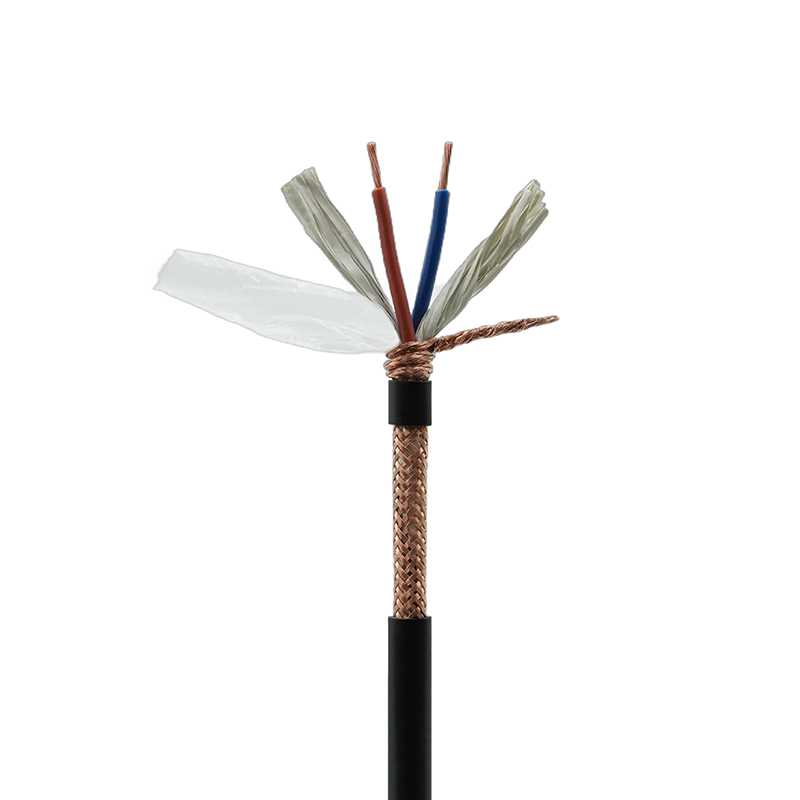
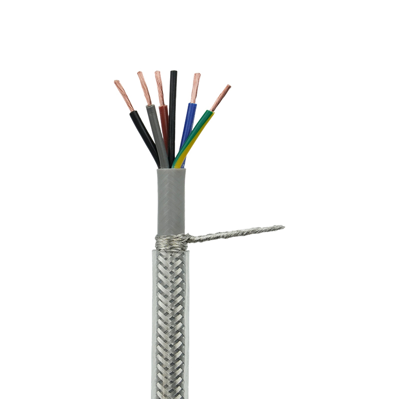
A variable frequency drive (VFD) delivers a pulse-width-modulated output that contains harmonics. Harmonics add to the RMS heating of the conductor even when the motor's fundamental current looks reasonable, and the fast voltage edges stress the insulation. For drive output circuits, a shielded cable with a symmetrical ground arrangement is the usual answer, and the ampacity should include margin for the added heating. The practical requirements covered in our guide to VFD cable requirements for shielded flexible drive wiring are worth checking before you finalize a size. For a new drive installation, an XLPE-insulated VFD flexible cable with copper braid shielding combines a 90°C rating with a continuous EMI shield in one assembly.
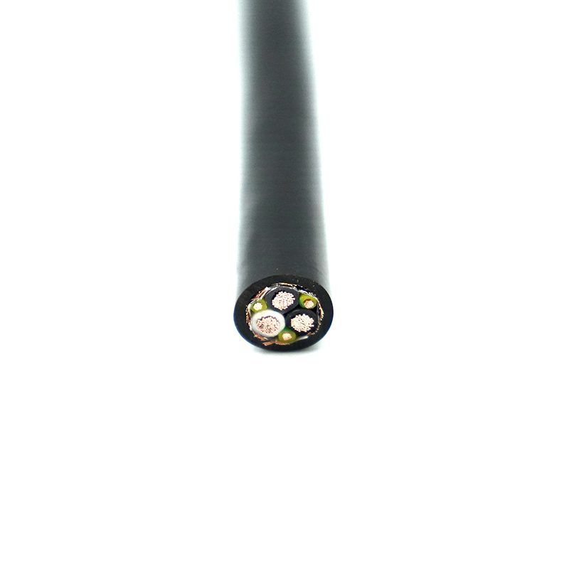 BPYJVRP XLPE Insulated PVC Sheathed Copper Braided Shielded VFD Flexible Cable SAs BPYJVRP XLPE Insulated PVC Sheathed Copper Braided Shielded VFD Flexible Cable Suppliers and Company in China, Junshuai offer Wholesal...View Product →
Drag chain and continuous flexing cables
Flex life is determined by stranding, conductor geometry, and jacket material, not by ampacity. The two interact in practice, though. In a cable carrier, conductors are usually bundled and enclosed, so the 0.80 factor for four to six conductors, or worse for larger bundles, must be applied to every core. Fine stranding that flexes well runs slightly hotter for the same cross-section because air gaps between strands reduce the effective conductive area, although the difference is small enough that standard ampacity tables remain valid. The jacket still has to survive the environment, whether PUR for oil resistance or TPU for abrasion, while the copper runs at the derated value.
Welding cables: duty cycle changes the calculation
Welding leads illustrate why "conditions of use" matters. A welding cable is designed for low-voltage, high-current service with a limited duty cycle, so it is rated using intermittent values rather than continuous ampacity. Its extra-fine stranding and flexible rubber jacket make it easy to coil and drag across a shop floor. A high-strength rubber welding cable of the right cross-section carries the welder's current without overheating, but the same cable would not be a valid choice for a 24-hour continuous power circuit rated on the continuous column.
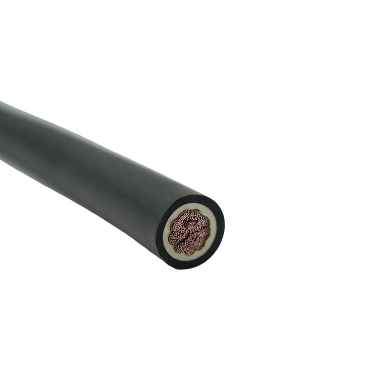 YH High-Strength Rubber Welding Cable Suppliers, Wholesale Company - Jiangsu JunAs YH High-Strength Rubber Welding Cable Suppliers and Company in China, Junshuai offer Wholesale High-Strength Rubber Welding Cable onli...View Product →
What to Specify When You Buy Cable
When you request a quote, a gauge number alone is not enough. A supplier needs to know the insulation and jacket materials, the temperature class, the number of current-carrying conductors, the ambient temperature, the installation method, and whether the circuit runs continuously or intermittently. Only then can the ampacity be verified against the correct table.
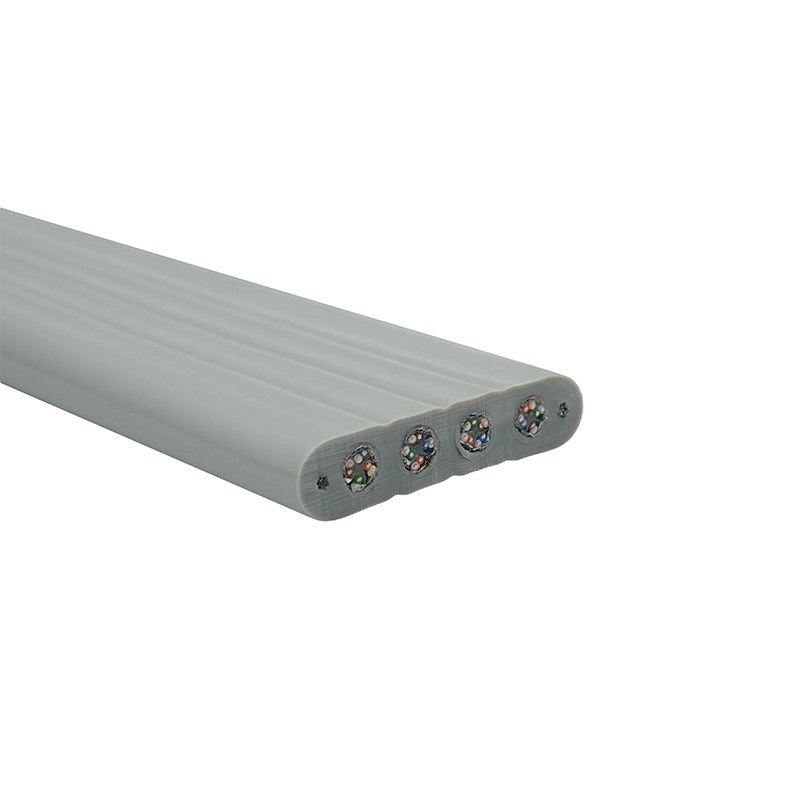
For equipment exported to North America, UL certification makes the rating verifiable during inspection. A UL-certified North American power wire with a printed temperature rating allows an electrical inspector to confirm that the conductor size matches the circuit protection. For dynamic applications, the same logic applies whether the cable is a drag chain type, a reeling cable, or a flat cable: the datasheet should state the ampacity under the operating conditions, not just the cross-section.
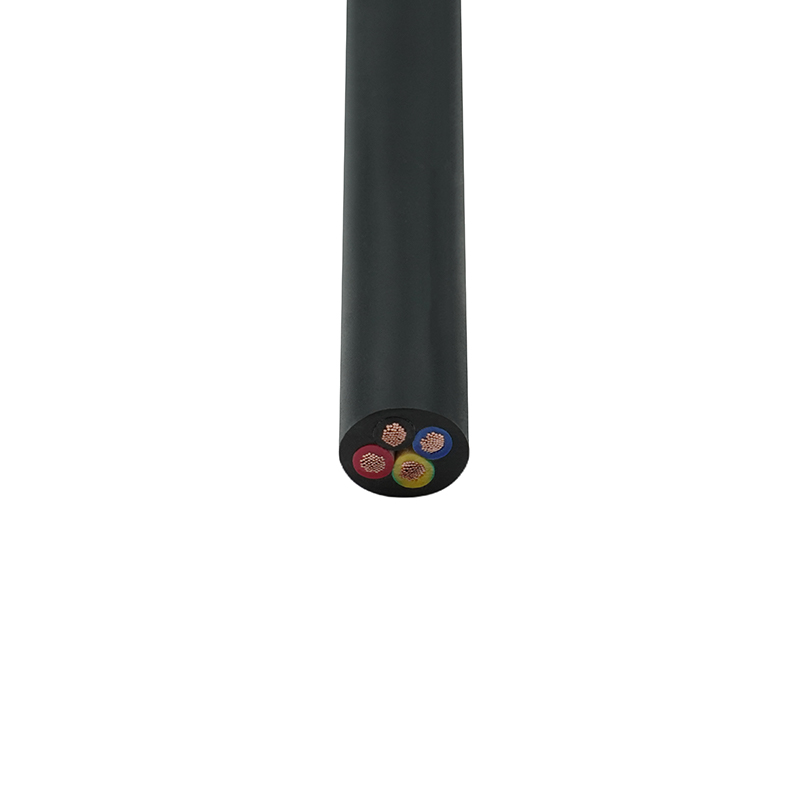 UL2586 UL Certified North American Power Wire Suppliers, Wholesale Company - JiaAs UL2586 UL Certified North American Power Wire Suppliers and Company in China, Junshuai offer Wholesale UL Certified North American Pow...View Product →
The reliable way to size any circuit is to work backwards from the load. Read the full-load current, select a conductor size and insulation rating, apply the ambient and bundling corrections, check voltage drop over the actual distance, and verify that the overcurrent protection matches the small-conductor rules. That process takes less than ten minutes and avoids the expensive, potentially dangerous mistake of treating a gauge number as a current rating.