EN
EN
 English
 русский
 Español
Welding Lead Sizes: AWG Chart, Ampacity & Cable Selection Guide (2026)
 Industry News
Content
- 1 Why Welding Cable Size Matters (More Than You Think)
- 2 Understanding AWG and the “Aught” System
- 3 The Ultimate Welding Cable Ampacity Chart (with Length Correction)
- 4 Step-by-Step: How to Select the Right Cable for Your Welder
- 5 Jacket Material Showdown: PVC vs. Rubber vs. Polyurethane (PUR)
- 6 Common Mistakes to Avoid When Sizing Welding Leads
- 7 When to Consider Custom Welding Cables
Why Welding Cable Size Matters (More Than You Think)
A welder in a busy fabrication bay once grabbed a #4 AWG cable for a 400‑amp stick job because it was the lead already on the machine. Twenty minutes in, the jacket turned tacky, the insulation smoked, and arc stability collapsed. The cable had become a fuse.
Undersizing a welding cable isn’t just an efficiency problem. It’s a safety and equipment‑life issue that hides in plain sight. Every time current runs through a conductor too small for the task, resistance skyrockets, and three things happen fast.
- Overheating. Copper heats beyond its rated temperature class, degrading insulation and inviting short circuits.
- Voltage drop. The arc sees fewer volts than the power source delivers, robbing penetration and bead consistency.
- Insulation failure. Repeated thermal stress cracks jackets, exposing conductors to moisture, oil, and ground‑fault hazards.
An undersized cable also wastes power. For a 200‑amp circuit at 100 feet, jumping just one AWG size too small can dissipate an extra 150 watts as heat along the lead, energy that never reaches the arc. Over a full shift, that’s real money — and real risk of a burn injury or machine damage.
Correct welding lead sizes are the foundation of a reliable welding setup. The numbers on a chart aren’t suggestions. They’re based on decades of thermal and electrical testing, and they demand respect.
Understanding AWG and the “Aught” System
The American Wire Gauge system feels backward at first. Smaller gauge numbers mean larger conductor cross‑sections. Once you pass #1 AWG, the scale shifts to the “aught” notation: 1/0 (one‑aught), 2/0 (two‑aught), 3/0, and 4/0. Each step in the aught range adds significant copper mass and current‑carrying ability.
A #4 AWG cable has roughly 21.2 mm² of copper cross‑section and a DC resistance of about 0.8 ohms per kilometer. By contrast, a 2/0 AWG lead packs 67.4 mm² with resistance dropping to 0.26 ohms per kilometer — that’s a threefold reduction in resistive losses for the same length run.
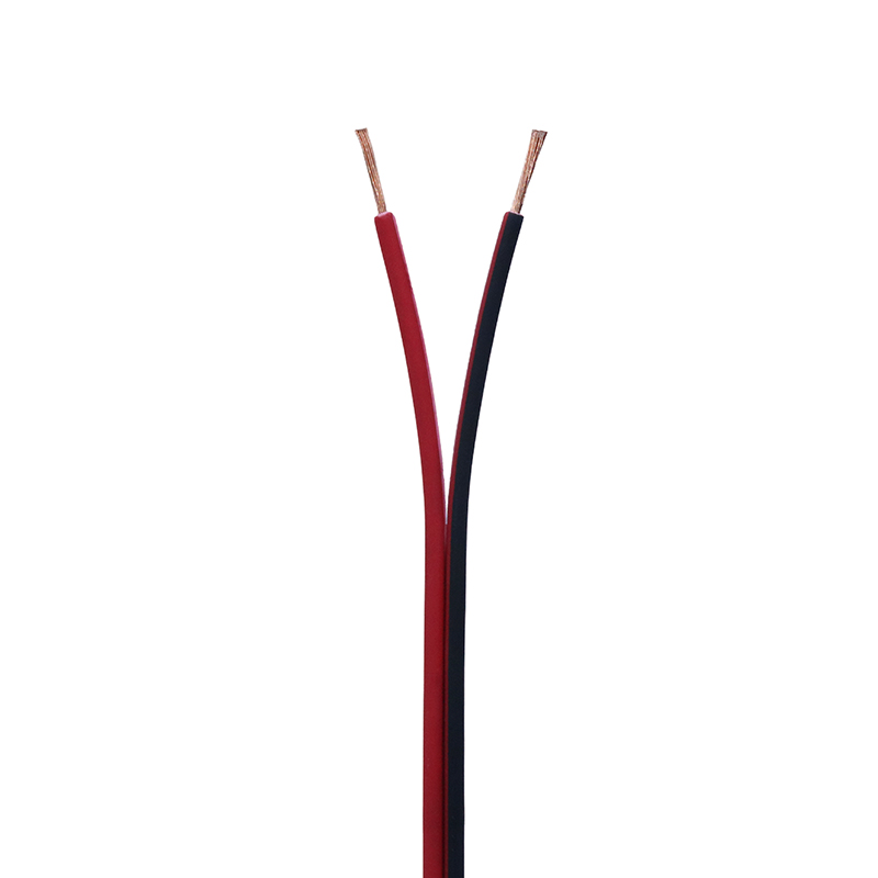
Welders often work with #4 through 4/0. A #4 cable handles light‑duty TIG or small MIG jobs under 150 amps. A 4/0 lead is the workhorse for heavy structural stick welding pushing 600‑amp bursts. The trick isn’t memorizing every diameter — it’s matching the AWG to your real‑world load and distance.
Metric cable sizes appear on imported equipment, usually labeled by cross‑sectional area in mm². A 35 mm² welding cable approximates #2 AWG, while 70 mm² sits near 2/0. When mixing metric and AWG, always cross‑check the ampacity rating of the specific construction rather than relying on a rough conversion.
The Ultimate Welding Cable Ampacity Chart (with Length Correction)
Standard ampacity charts assume a 25‑foot or 50‑foot circuit, but welding leads often stretch to 100 feet and beyond. Resistance accumulates linearly, so a cable that handles 300 amps at 25 feet may safely carry only 190 amps at 100 feet. The table below bakes in those real‑world deratings for a 60% duty cycle, which mirrors most shop and field work.
| AWG Size | 25 ft | 50 ft | 100 ft | 150 ft |
|---|---|---|---|---|
| #4 | 150 A | 120 A | 90 A | 70 A |
| #2 | 210 A | 170 A | 120 A | 95 A |
| #1 | 250 A | 200 A | 150 A | 115 A |
| 1/0 | 310 A | 250 A | 180 A | 140 A |
| 2/0 | 370 A | 300 A | 220 A | 170 A |
| 3/0 | 430 A | 350 A | 260 A | 200 A |
| 4/0 | 510 A | 410 A | 310 A | 240 A |
These numbers assume good connections, free air circulation, and no bundling with other hot leads. If you work in a confined engine compartment or run the cable through a coiled reel, the effective ampacity can drop another 15–25%. When in doubt, go up one AWG size — the slight increase in upfront cost buys a much wider safety margin.
Notice that at 150 feet, a 4/0 cable is barely adequate for a 240‑amp load. That’s a common scenario in shipyards and structural steel erection. The takeaway: length is the silent amp‑killer.
Step-by-Step: How to Select the Right Cable for Your Welder
Every welding cable size decision boils down to four variables. Get them right, and you’ll never waste time troubleshooting arc wander or melted lugs.
- Determine the maximum output current of your power source. Look at the nameplate rating, not the dial setting you typically use. A 300‑amp MIG machine can deliver its full output even if you normally weld at 220 amps. Size for the peak, not the habit.
- Measure the total circuit length. Add the electrode cable, work clamp cable, and any jumpers or extensions. The current travels the entire loop — so a 50‑foot electrode lead plus a 50‑foot work lead equals a 100‑foot circuit. Miss this, and you’ll undersize by at least one gauge.
- Factor in the duty cycle. Most welders run at a 60% duty cycle. Multiply the maximum output current by the square root of the duty‑cycle fraction. For 300 amps at 60%, that’s about 232 effective amps. Then apply the length correction from the ampacity chart. If the result exceeds the rating of your chosen AWG, move up.
- Select the cable and round up. Use the chart to find the AWG that comfortably meets your corrected current. When the number lands on a borderline, always choose the next larger size. The extra copper isn’t just insurance; it keeps the cable cooler and more flexible over its life.
After these four steps, you’ll have a cable size that won’t let you down. A practical shortcut: for typical shop welding with a 250‑amp MIG welder and 50‑foot total circuit, a 1/0 cable is the solid middle ground. For field work with 100‑foot runs, 2/0 or 3/0 becomes the minimum.
Jacket Material Showdown: PVC vs. Rubber vs. Polyurethane (PUR)
Ampacity gets all the attention, but the jacket material dictates how long the cable survives in your environment. Three materials dominate the market, and each has a distinct personality.
PVC jackets are inexpensive and flame‑retardant, yet they stiffen in cold weather and crack rapidly when exposed to oil and constant flexing. Rubber compounds — often EPDM or neoprene — offer strong oil resistance, excellent flexibility, and reasonable durability at sub‑zero temperatures. Polyurethane (PUR) jackets sit at the top of the performance pyramid, combining extreme abrasion resistance, near‑effortless flexibility, and the ability to shrug off oils and greases.
The table below compares them head‑to‑head for the harsh conditions found in typical welding environments.
| Property | PVC | Rubber (EPDM / Neoprene) | Polyurethane (PUR) |
|---|---|---|---|
| Abrasion resistance | Low | Good | Excellent |
| Oil resistance | Moderate | Good | Excellent |
| Low‑temperature performance | Poor (stiffens below -10 °C) | Good (flexible to -30 °C) | Excellent (flexible to -40 °C) |
| Flexibility | Moderate | High | Very high |
| Relative cost | Low | Moderate | High |
For most fabrication shops and outdoor construction, a high‑strength rubber welding cable hits the sweet spot between cost and durability. The rubber jacket withstands dragged‑over‑concrete abuse, occasional oil splashes, and the rough handling typical on a job site. In automated welding cells or robotic arms, where flex cycles reach into the millions, PUR jacketed reeling cables become the only logical choice. They resist cuts that would slice rubber in half and maintain full flexibility at bitterly cold temperatures.
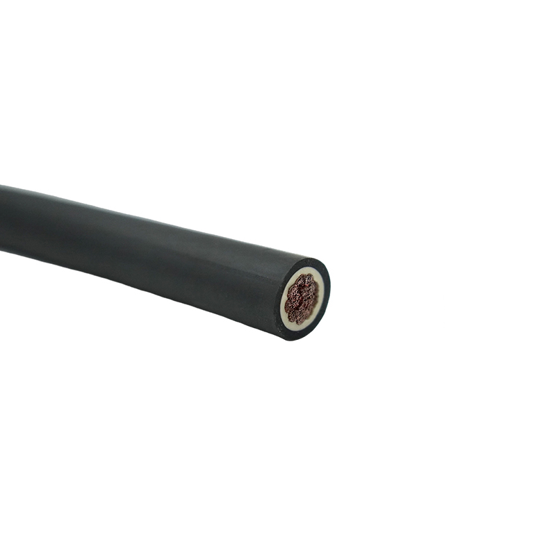
One critical detail: never use an indoor‑only PVC jacket cable outdoors for more than a few months. UV radiation embrittles PVC, leading to surface cracking that lets moisture reach the copper. An EPDM or neoprene jacket, properly formulated, resists UV for years without significant degradation.
Common Mistakes to Avoid When Sizing Welding Leads
Experience teaches hard lessons. These are the missteps that plant electricians and pipeline welders see again and again — and how to dodge them from day one.
- Mistake: Using the machine’s nameplate amps without length correction. The nameplate rating assumes a zero‑resistance connection. A 100‑foot circuit can drop 4 to 6 volts, robbing you of both power and safety margin. Always apply the length derating from a verified chart.
- Mistake: Ignoring the total circuit length. Counting only the electrode lead while forgetting the work clamp return path is the single most common source of undersizing. Measure both leads and sum them, every time.
- Mistake: Substituting standard electrical building wire for welding cable. THHN or Romex may have the right copper cross‑section, but they lack the high‑strand‑count construction that gives a welding lead its flexibility. They also have insulation not rated for the high‑frequency ripple current present in many inverter‑based welders. The cable will eventually fail, often at a lug connection, causing arcing and fire risk.
- Mistake: Buying a size that fits “most” jobs. A 1/0 cable might cover 80% of your work — until one bridge girder job requires a 150‑foot run at 350 amps. Stock at least one gauge above your everyday need so you’re not caught short.
- Mistake: Overlooking physical cable dimensions. A 4/0 welding lead has an outer diameter around 0.75 inches and a minimum bend radius of about 5 inches. If the cable has to snake through a tight machine frame, a smaller‑gauge high‑flex variant may be required, balanced against ampacity.
Each error traces back to the same root cause: treating the cable as an afterthought. The lead is a critical electrical component, not a commodity hose.
When to Consider Custom Welding Cables
Off‑the‑shelf welding cables handle perhaps 90% of applications. The remaining 10% demand a tailored solution — and that’s where downtime and frustration multiply if you delay the decision.
Three scenarios point clearly toward a custom cable assembly:
- Unusual lengths beyond 150 feet. Voltage drop becomes the dominant design factor. A custom cable can incorporate a precisely calculated oversized conductor to keep arc voltage within limits, plus a robust strain‑relief jacket designed for long pulling distances.
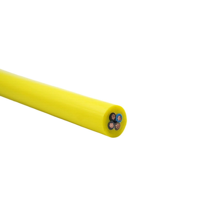
- Extreme environmental exposure. Continuous immersion in water, prolonged contact with hydraulic fluids, or operation inside a furnace zone calls for jacket and insulation combinations that aren’t stocked on hardware shelves. A custom‑engineered solution merges the right conductor class with a proprietary jacket compound.
- Specialized terminations and connectors. When the cable must directly plug into a proprietary stud, twist‑lock, or robotic coupler, molded‑on terminations guarantee a durable, low‑resistance interface that field‑applied lugs can’t match.
Custom doesn’t necessarily mean exotic. Often it’s simply a matter of selecting the right conductor stranding, jacket material, and connector in a single assembly. For projects that demand a non‑standard welding lead, explore the range of engineered cable options that can be built to your exact specifications.