 EN
EN
 English
 русский
 Español
Braided Metal Cable Selection Guide: 7x7, 7x19, 1x19 & Material Comparison
 2026.07.08
 Industry News
Content
- 1 What Is a Braided Metal Cable?
- 2 Braided Metal Cable vs. Wire Rope: Key Differences
- 3 Common Braid Constructions: 7x7, 7x19, and 1x19
- 4 Material Selection: Stainless Steel vs. Galvanized Steel
- 5 How to Choose the Right Diameter and Strength
- 6 Application-Specific Recommendations
- 7 Installation Best Practices for Braided Metal Cable
- 8 Where to Buy Braided Metal Cable (and What to Look For)
What Is a Braided Metal Cable?
A braided metal cable is a load-bearing assembly formed by weaving multiple strands of thin metal wire around a central core in a symmetrical helical pattern. Unlike solid rod or single-strand wire, this construction distributes tensile stress across dozens of individual filaments. The result is a product that retains high break strength while delivering a bend radius that solid alternatives cannot match.
The defining characteristic here is the weave itself. Each strand is wound in a fixed lay direction, creating a tubular braid that compresses slightly under load without sacrificing structural integrity. This woven architecture provides inherent flexibility, strong resistance to fatigue cracking, and a degree of self-damping against vibration. In industrial environments, these properties translate directly into longer service intervals and fewer sudden failures.
You will see braided metal cable specified across a wide spectrum: aircraft control linkages, architectural tension systems, crane pendants, marine rigging, and automation equipment. In many of these applications, the cable must handle not only static tension but also thousands of small bending cycles as pulleys engage or structures sway. The braided form handles that dual demand better than any other circular metallic tension element of comparable diameter.
Braided Metal Cable vs. Wire Rope: Key Differences
Many buyers use the terms interchangeably, but braided metal cable and traditional wire rope differ in construction, flexibility, and optimal use. Wire rope consists of wires twisted concentrically into strands, which are then twisted around a core, while a braided cable uses an interwoven pattern that resembles a tubular mesh. That structural distinction creates a meaningful gap in performance.
Braided cable excels where tight bend radii and frequent flexing dominate the duty cycle. Its weave allows individual wires to slide slightly against one another, reducing internal friction and preventing the kinking that plagued early-generation wire ropes. Wire rope, by contrast, delivers superior crush resistance and handles heavy, static loads on large-diameter sheaves with greater efficiency and often lower cost per ton of load.
| Property | Braided Metal Cable | Wire Rope (IWR/Fiber Core) |
|---|---|---|
| Flexibility (cycle life) | High — survives thousands of small-radius bends | Moderate — larger minimum bend radius required |
| Kink resistance | Excellent — weave geometry resists spontaneous kinks | Poor to fair — twisted strands tend to kink under low tension |
| Crush resistance | Moderate — weave can flatten under heavy cross loads | High — concentric strands resist radial compression better |
| Installation ease | Easier in tight spaces; no heavy sheave set needed | Requires handling equipment for large diameters |
For applications that demand both continuous flexing and controlled tension — such as hoist retraction cables on automated machinery — braided cable is almost always the better choice. Wire rope still dominates in heavy overhead crane lifting and structural stays, where loads are static or move slowly over large sheaves. The decision often comes down to whether the cable must survive dynamic bending fatigue or simply hold a static load.
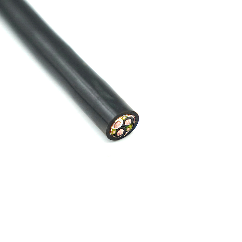
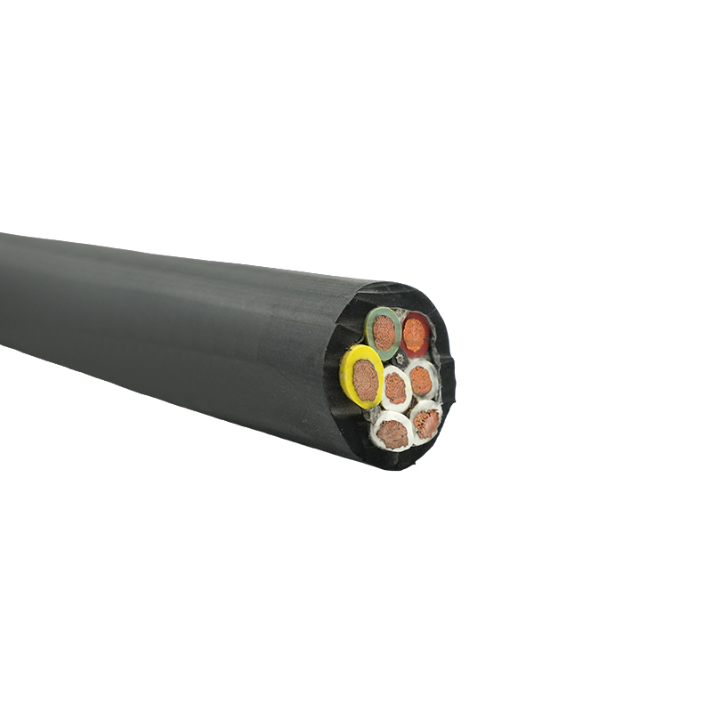
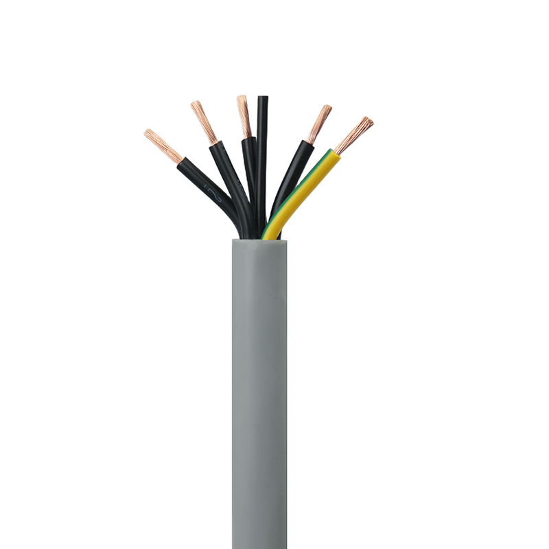
When moving loads through complex routing paths in machinery, you may need a cable that goes beyond what either braided metal cable or wire rope can offer. In those scenarios, a specialized JZ-500 highly flexible control cable designed for energy chains delivers the bending endurance and electrical conductivity required in automated production lines.
Common Braid Constructions: 7x7, 7x19, and 1x19
Selecting the right braid structure is the single most important specification decision. The three main patterns — 7x7, 7x19, and 1x19 — each represent a different trade-off between flexibility, abrasion resistance, and fatigue life. The naming convention tells you exactly what is inside: the first number indicates the count of strands, and the second indicates the number of wires within each strand.
| Construction | Strand/Wire Count | Flexibility & Fatigue | Best Application |
|---|---|---|---|
| 7x7 | 7 strands of 7 wires each | Moderate flexibility; good abrasion resistance | General-purpose rigging, gym equipment, static tension members |
| 7x19 | 7 strands of 19 wires each | High flexibility; best fatigue life | Aircraft control cables, running rigging, overhead door cables, dynamic hoisting |
| 1x19 | 1 strand of 19 wires | Low flexibility; highest tensile stiffness | Standing rigging, architectural bracing, push-pull controls |
7x7 construction is the workhorse for static and low-cycle applications. Its thicker individual wires yield a cable that resists external wear but stiffens noticeably under tight bends. 7x19 is the go-to whenever a cable must navigate pulleys or sheaves. The finer wire filaments tolerate repeated bending without work-hardening and cracking as quickly. 1x19 behaves almost like a solid rod with minimal stretch, making it ideal for permanent installations where dimensional stability matters more than re-routing.
Material Selection: Stainless Steel vs. Galvanized Steel
The base metal determines how the cable performs over years of exposure to moisture, chemicals, and temperature swings. Stainless steel and galvanized carbon steel both have their place, but their cost and corrosion behaviors diverge sharply in specific environments.
Stainless steel 304 offers strong resistance to atmospheric corrosion and many mild chemicals. For marine and offshore settings, 316 stainless steel is the clear winner. Its 2 to 3 percent molybdenum content creates a passive layer that withstands chloride-induced pitting in ways that 304 cannot match. In salt spray test data, 316 braided cables maintain 90 percent of their original tensile strength after 1,000 hours, while 304 shows noticeable pitting and galvanized steel begins to lose zinc at the cut ends within 300 hours.
Galvanized steel provides a high-strength, cost-effective solution for dry indoor or mild outdoor environments. The zinc coating sacrifices itself to protect the underlying steel, but once the coating is consumed at wear points or cut edges, red rust appears rapidly. For a quick turnaround projects with a tight capital budget and a planned replacement window under five years, galvanized steel often makes financial sense. For critical infrastructure where a single cable failure halts operations, the premium for 316 stainless pays for itself in avoided downtime.
| Environment | Recommended Material | Expected Service Life (untouched) |
|---|---|---|
| Indoor, climate-controlled | Galvanized steel | 10+ years |
| Outdoor, inland (midwest) | 304 stainless or galvanized | 8–12 years / 5–8 years |
| Coastal or industrial with chlorides | 316 stainless steel | 12–15 years |
| Submerged (freshwater) | 304 or 316 stainless | 10–15 years |
| Submerged (seawater) | 316 stainless steel | 8–12 years |
How to Choose the Right Diameter and Strength
Braided metal cable is always specified by diameter, but the only number that matters for safety is its minimum break strength (MBS). MBS represents the force at which a new, undamaged cable will fail in a straight tensile pull. You should never approach that number in operation.
Industry best practice mandates a safety factor of at least 5:1 for static loads and up to 10:1 for dynamic lifting applications involving personnel or unpredictable shock loads. This means your working load limit (WLL) equals MBS divided by the safety factor. A cable with a 2,000-pound MBS used in a dynamic setting should never see more than 200 pounds of tension during normal cycles. Exceeding that margin accelerates fatigue and can cause sudden, catastrophic failure.
| Diameter (inch) | Approx. MBS (lbs, 304 SS) | Safe Work Load at 5:1 |
|---|---|---|
| 1/16″ | 480 | 96 lbs |
| 3/32″ | 920 | 184 lbs |
| 1/8″ | 1,760 | 352 lbs |
| 3/16″ | 3,700 | 740 lbs |
| 1/4″ | 6,400 | 1,280 lbs |
Always confirm the exact MBS from the manufacturer's datasheet for the specific grade and construction you are ordering. Variations in manufacturing process and alloy chemistry can shift break strength by plus or minus 5 percent, which is enough to change the safety factor margin when working near the edge of the envelope.
Application-Specific Recommendations
Static Suspension and Architectural Loads
For canopies, tensioned facades, or lighting grids, 1x19 stainless steel remains the standard. Its low stretch and clean appearance require no ongoing adjustment once properly tensioned. Corrosion resistance will be a priority if the installation is exposed to weather, making 316 the default choice in coastal cities.
Dynamic Traction and Repeated Bending
Any application where the cable runs around a pulley demands 7x19 construction. This includes overhead door cables, stage rigging, and fitness equipment. The thinner wires inside the strands can flex millions of times without work-hardening to the point of fracture. When combined with a 316 stainless substrate, you get a maintenance cycle that can stretch to 5 years or more even in damp service bays.
Underwater and Submerged ROV Applications
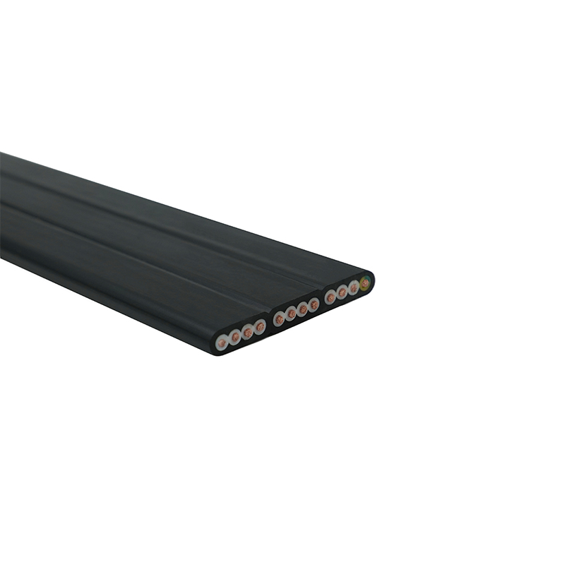
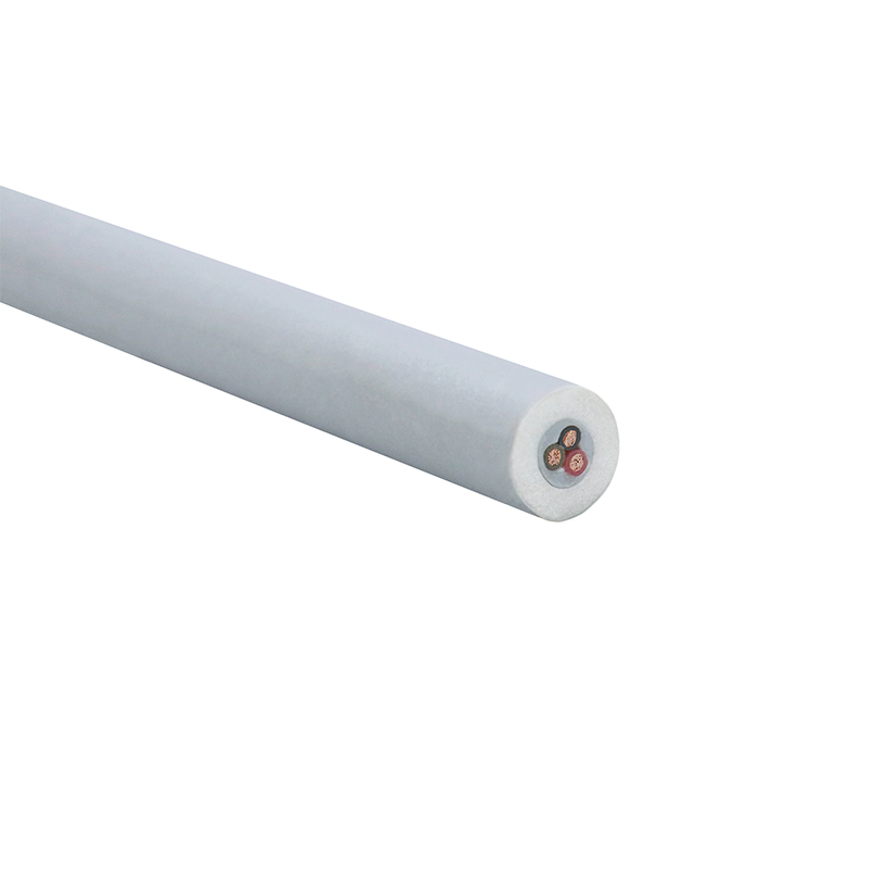
Subsea environments add two complications: corrosion and weight. A conventional braided steel cable sinks and introduces drag. For tethered underwater robots and inspection equipment, the optimal solution combines strength with positive buoyancy. Products like a ROV floating cable integrate a braided strain member with a buoyant jacket, giving the tether neutral buoyancy while still resisting the pulling forces without damaging the internal conductors.
Data and Control Circuits with Mechanical Protection
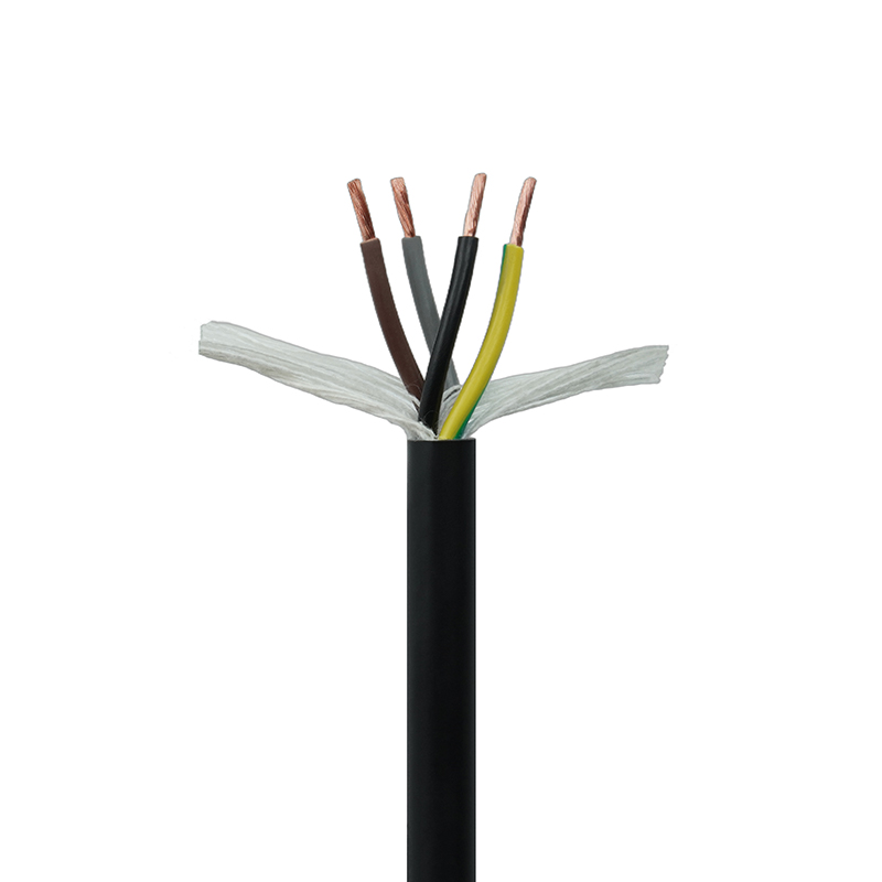
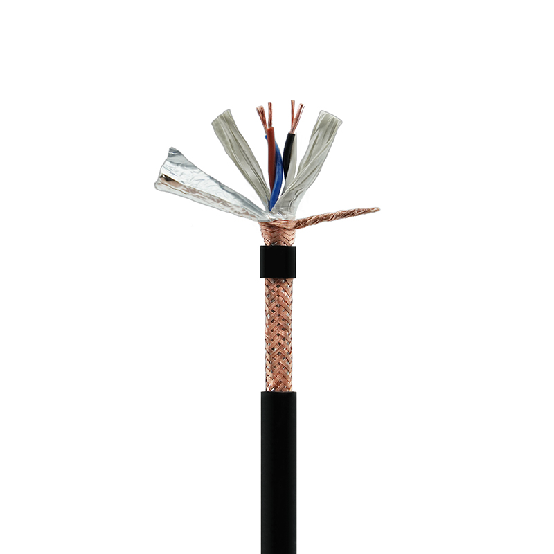
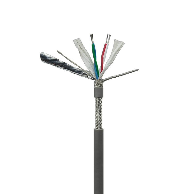
When the braided metal structure serves double duty as a shield against electromagnetic interference, the choice of braid angle and coverage percentage becomes critical. For RS485-based industrial networks that must survive both mechanical abrasion and signal corruption, a shielded cable with a tight copper braid shield is the proven approach. The RS485 communication cable for industrial control systems illustrates how a braided metal layer can prevent data errors while also reinforcing the cable against cuts and crushing in crowded cable trays.
High-Temperature and Extreme Environments
Standard galvanized cables lose strength rapidly above 400 degrees Fahrenheit due to zinc migration and steel creep. Stainless steel 304 and 316 retain useful strength up to 1,500 degrees Fahrenheit, but only in short-duration exposures. For sustained high heat, you must de-rate the MBS by at least 20 percent and consider ceramic or high-nickel alloys that fall outside the scope of standard braided metal cable specifications.
Installation Best Practices for Braided Metal Cable
Getting the cut and termination right eliminates at least half of all premature cable failures. A poorly crimped fitting will slip under load, and a frayed end will snag and unravel during routing. Follow these steps to ensure the assembly meets its design life.
- Measure and mark under light tension. Lay the cable straight with enough tension to remove coil set. Mark the cut point with a felt-tip pen or clamp. Cutting a slack cable yields a length that will stretch on first loading.
- Use a sharp, purpose-built cutter. Diagonal cutters crush the strands and create burrs. A hydraulic cable cutter or high-leverage shear delivers a clean, square cut that seats securely in the fitting.
- Slide the compression sleeve fully onto the cable. Insert the cable end through the sleeve and form the loop or thimble, then bring the tail back through the sleeve. Leave about one diameter of cable protruding past the sleeve before crimping. This projection gives the inspector a visual indication that the cable filled the fitting.
- Crimp with the correct die set. Use a tool that matches the sleeve manufacturer's specified die profile and force. Under-crimping leaves microscopic gaps that permit wire pull-out. Over-crimping cold-works the metal and can crack the sleeve, reducing its holding power.
- Inspect and proof load. Apply at least twice the working load to the assembly and hold for 30 seconds. Check for any cable slippage within the sleeve. Mark the cable at the sleeve exit with a permanent marker to detect future movement during periodic inspections.
Skipping the proof load step is the most common cause of field failures, especially with smaller diameter cables where a few thousandths of an inch of slip may go unnoticed until the assembly fully separates.
Where to Buy Braided Metal Cable (and What to Look For)
Sourcing braided metal cable goes beyond picking a diameter. A reliable purchase starts with a clear specification document that addresses five parameters:
- Diameter: Confirmed to the nearest 1/64 inch or 0.5 mm.
- Construction: 7x7, 7x19, or 1x19 — never accept “braided steel cable” as a sufficient description.
- Material and grade: 304 SS, 316 SS, or galvanized carbon steel, with a mill certificate if the application is safety-critical.
- Length: Specified in feet or meters, with a tolerance of plus 2 percent / minus zero so you never come up short.
- End termination type: Swaged stud, threaded ball, plain end, or fitted loop, confirmed against your integration drawing.
Look for suppliers who provide third-party load test reports and who maintain batch traceability. Certifications such as UL, CE, or CCC indicate that the manufacturer operates under a quality management system with periodic audits. For industrial and marine projects, insisting on a Certificate of Conformance and a break test sample can prevent weeks of rework later.