 EN
EN
 English
 русский
 Español
Cable Size and Amps Chart: How to Read Ampacity and Choose the Right Cable
 2026.09.21
 Industry News
Content
Search for a cable size and amps chart and you will find dozens of tables that look confident and complete. Most of them are not wrong; they are simply incomplete. The current figure printed beside a conductor size is a baseline value, measured under a specific set of conditions: a defined ambient temperature, a limited number of bundled conductors, and a maximum conductor temperature set by the insulation material. Move that cable into a hot plant room, bundle it into a conduit with eight other circuits, or run it at full load for hours at a time, and the safe current drops.
This guide explains what the numbers in a cable size and amps chart really mean, how to adjust them for the conditions on your site, and how to connect the result to a cable construction that will still be in service years from now.
What a Cable Size and Amps Chart Actually Measures
Ampacity is the maximum current a conductor can carry continuously without pushing its insulation above its rated temperature. Current flowing through copper meets resistance, resistance produces heat, and that heat has to travel out through the insulation, through any shield or braid, through the jacket, and finally into the surrounding air. A cable size and amps chart is simply a summary of how well that journey works for each conductor size under one standard set of test conditions.
Two sizing systems, one table
Metric cables are sized by nominal conductor cross-section in square millimetres. North American practice uses AWG, a diameter-based scale on which a smaller number means a thicker conductor, plus kcmil for the largest sizes. A 4 mm² conductor and a 12 AWG conductor are close enough that they are often used for the same duties, but they are not identical, and a chart that mixes the two systems without labelling the columns clearly will lead you to the wrong answer. Check which column you are reading before you trust it.
The insulation rating sets the ceiling
The same copper conductor appears with three different current figures in most charts because its insulation might be rated for 60 °C, 75 °C or 90 °C. A higher permitted conductor temperature means more current before the insulation is at risk, which is why cross-linked polyethylene and silicone constructions outperform basic PVC. One caution: the weakest link is not always the conductor. A 90 °C core inside a 70 °C jacket, or terminated in a connector rated for 60 °C, still limits the circuit to the lowest rating in the chain.
Copper Cable Size and Amps Chart
The table below shows typical copper ampacities for common conductor sizes. It assumes a 30 °C ambient temperature and no more than three current-carrying conductors in a raceway or cable, which is the basis most published tables use.
| Cross-section (mm²) | AWG / kcmil | 60 °C insulation (A) | 75 °C insulation (A) | 90 °C insulation (A) |
|---|---|---|---|---|
| 2.1 | 14 AWG | 15 | 20 | 25 |
| 3.3 | 12 AWG | 20 | 25 | 30 |
| 5.3 | 10 AWG | 30 | 35 | 40 |
| 8.4 | 8 AWG | 40 | 50 | 55 |
| 13.3 | 6 AWG | 55 | 65 | 75 |
| 21.2 | 4 AWG | 70 | 85 | 95 |
| 33.6 | 2 AWG | 95 | 115 | 130 |
| 53.5 | 1/0 AWG | 125 | 150 | 170 |
| 85.0 | 3/0 AWG | 165 | 200 | 225 |
| 107 | 4/0 AWG | 195 | 230 | 260 |
One pattern is worth remembering: ampacity does not grow in step with cross-section. Doubling the copper area adds roughly 40 to 50 percent more current, not 100 percent, because a larger conductor has proportionally less surface area from which to shed heat. That is exactly why long runs are often upsized for voltage drop rather than for ampacity, and why the chart alone never settles a cable selection.
Temperature Correction Comes First
Charts are normally published for a 30 °C ambient. If your cable runs where the air is hotter, above a furnace, inside a sealed cabinet, in a foundry, or beside a solar inverter, the baseline figure must be multiplied by a correction factor.
| Ambient temperature (°C) | Correction factor |
|---|---|
| 21 to 25 | 1.05 |
| 26 to 30 | 1.00 |
| 31 to 35 | 0.94 |
| 36 to 40 | 0.88 |
| 41 to 45 | 0.82 |
| 46 to 50 | 0.75 |
| 51 to 55 | 0.67 |
| 56 to 60 | 0.58 |
A worked example makes the effect obvious. An 8 AWG conductor rated at 50 A for 75 °C insulation, installed where the ambient reaches 45 °C, gives 50 × 0.82 = 41 A before any other adjustment. Design against 41 A, not 50 A, and add a margin if the load is continuous.
Derating Factors the Chart Leaves Out
Temperature is only the first adjustment. The following factors also move the usable current, and in a busy industrial installation several of them apply at the same time.
- Number of bundled conductors. When more than three current-carrying conductors share a raceway, tray or bundle, they heat each other. Typical multipliers range from about 0.8 for four to six conductors down to 0.7 or less for seven to nine.
- Installation method. A cable in free air cools far better than the same cable in a closed conduit, in a wall cavity, or buried under thermal insulation. Charts should state which method they assume.
- Continuous duty. Loads that run for three hours or more are usually treated as continuous, and the conductor is sized at 125 percent of the load current. Intermittent loads such as welding or hoisting can be treated more generously.
- Harmonics. In three-phase four-wire systems feeding non-linear loads, triplen harmonics accumulate in the neutral, so the neutral conductor may need to be the same size as the phase conductors or larger.
- Mechanical flexing. Repeated bending changes the stranding and therefore the effective copper area, so flexible applications deserve extra headroom.
Copper or Aluminium: One Table, Two Answers
Aluminium conductors need to be roughly two AWG sizes larger than copper to carry the same current, and they behave differently at terminations because of oxide formation and thermal expansion. A chart built for copper must never be read as if it applied to aluminium. For a fuller comparison of how the two materials are treated in published standards, our guide to copper versus aluminium ampacity walks through the ratings side by side. For sizing purposes, the short version is simple: always confirm which conductor material the numbers belong to.
Where the Chart Meets Real Cable Construction
Every ampacity table assumes a generic conductor. Cables actually installed on machines carry shields, braids, fillers, drain wires, steel support elements and thick jackets, and each layer sits between the conductor and the air. Construction does not change the physics, but it does change how much margin is sensible.
North American projects sized in AWG
When the installation follows North American practice, the chart you work from will be in AWG, and the cable itself will usually need a UL listing before an inspector will sign it off. The power wire below is manufactured and listed for exactly that kind of work, in AWG sizes that map directly onto the mainstream ampacity tables, so the number you read in the chart and the number on the reel agree.
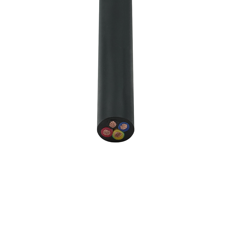 UL Certified North American Power Wire (UL2586)Product Positioning: An "all-round equipment wiring cable" that balances high-voltage power and multi-core integration, focusing on machine tools and high-temperature ...View Product →
Cables that flex millions of times
Continuous flexing is the factor ampacity tables handle worst. A drag chain cable may be bent thousands of times a day, which is why its conductor is finely stranded so individual wires do not work-harden and fracture. Fine stranding also means slightly less copper for a given overall diameter, so it is good practice to keep a generous margin on the chart figure and to choose a cable engineered for flexing rather than a general-purpose cable that happens to fit the terminal.
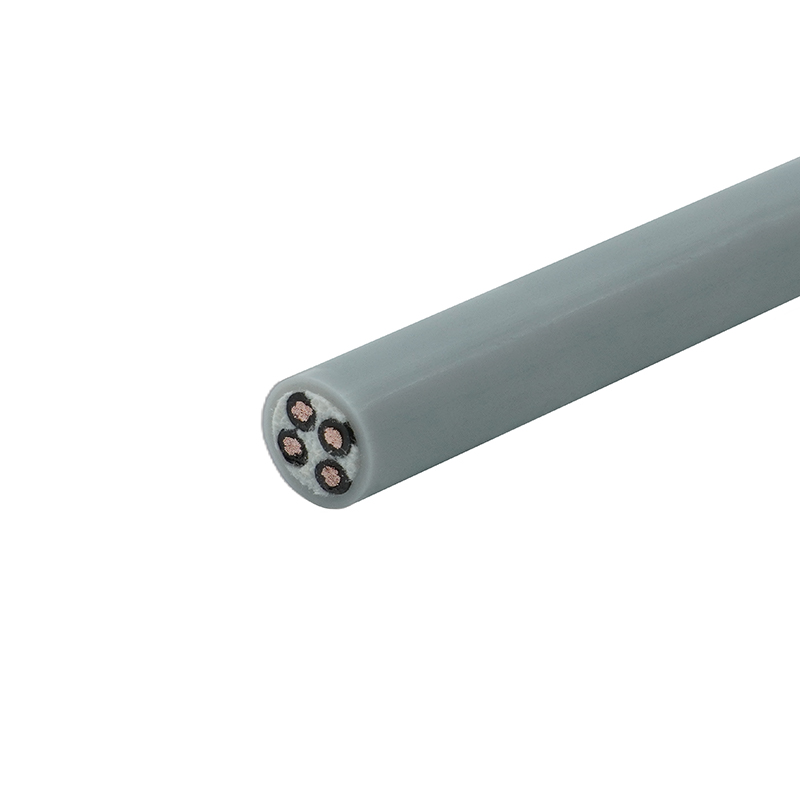 High-Flex Polyurethane Drag Chain Control Cable (TRVV-PUR)Product Positioning: An unshielded weather-resistant towline cable, focusing on power transmission in extreme environments.View Product →
Intermittent duty and high current
Welding leads, hoist motors and starting circuits draw large currents for short periods, then pause. Because heat has time to dissipate between operations, a rubber welding cable can safely run at a higher current density than a chart written for continuous duty suggests. Size for the duty cycle and the real ambient, not only for the peak ampere reading, and keep the conductor stranding appropriate for the handling the cable receives.
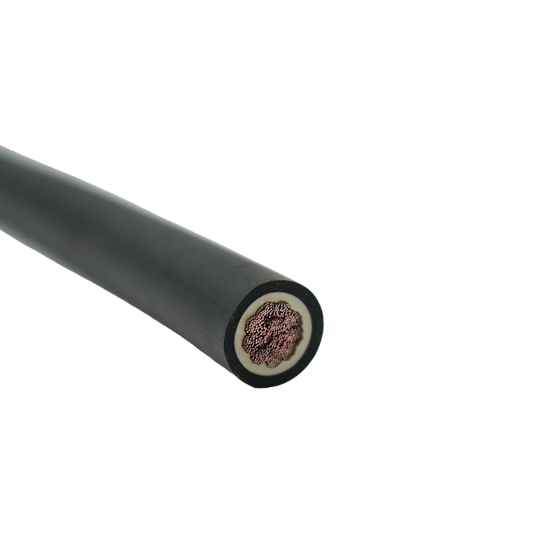 High-Strength Rubber Welding Cable (YH)Product Positioning: A dedicated low-voltage high-current cable for welding machines, focusing on low impedance and high current-carrying capacity. It is suitable for ...View Product →
A Practical Selection Checklist
Working from the load back to the cable is quicker than starting with the chart and hoping it fits.
- Establish the actual load current, and apply a continuous-duty margin, typically 125 percent.
- Read the baseline ampacity from the chart for the conductor size and insulation class you intend to use.
- Apply the ambient temperature correction factor for the hottest realistic location, not the average.
- Apply bundling and installation derating factors for the real route.
- Check voltage drop over the full circuit length and upsize if the drop exceeds the limit your equipment tolerates.
- Confirm the construction, stranding, shielding and jacket material suit the mechanical and chemical environment.
- Verify the certification your target market requires, such as UL, CE or CCC, before the order is placed.
Read correctly, a cable size and amps chart answers one question well: how much current a conductor can carry in a defined and fairly gentle environment. Everything the chart cannot know, the real temperature of the room, the number of cables in the tray, the way the cable moves, and the length of the run, is where the engineering actually happens. Get both halves right and the cable will outlast the equipment it feeds.
If you would rather work through a specific application, our specialty cable manufacturing team can review your current, route and environment, and recommend the construction and conductor size that fits the job rather than the average.